Multifrequency directional-diagram reconfigurable antenna based on double-open resonant ring

A split resonant ring and reconfigurable antenna technology, which is applied to resonant antennas, antennas, and devices that enable antennas to work in different bands at the same time, can solve the problems of complex reconfigurable antenna structures and cannot work at the same time, and achieve easy mass production Production and integration, easy processing, small size effect

Inactive Publication Date: 2012-09-26
36TH RES INST OF CETC +1
View PDF4 Cites 18 Cited by
  • Summary
  • Abstract
  • Description
  • Claims
  • Application Information

AI Technical Summary

Problems solved by technology

[0004] The purpose of the present invention is to solve the problem that the existing reconfigurable antenna has a complex structure and cannot work simultaneously at multiple different frequencies, and then provides a multi-frequency pattern reconfigurable antenna based on a double split resonator ring

Method used


Image

  • Multifrequency directional-diagram reconfigurable antenna based on double-open resonant ring
  • Multifrequency directional-diagram reconfigurable antenna based on double-open resonant ring
  • Multifrequency directional-diagram reconfigurable antenna based on double-open resonant ring

Examples


specific Embodiment approach 1

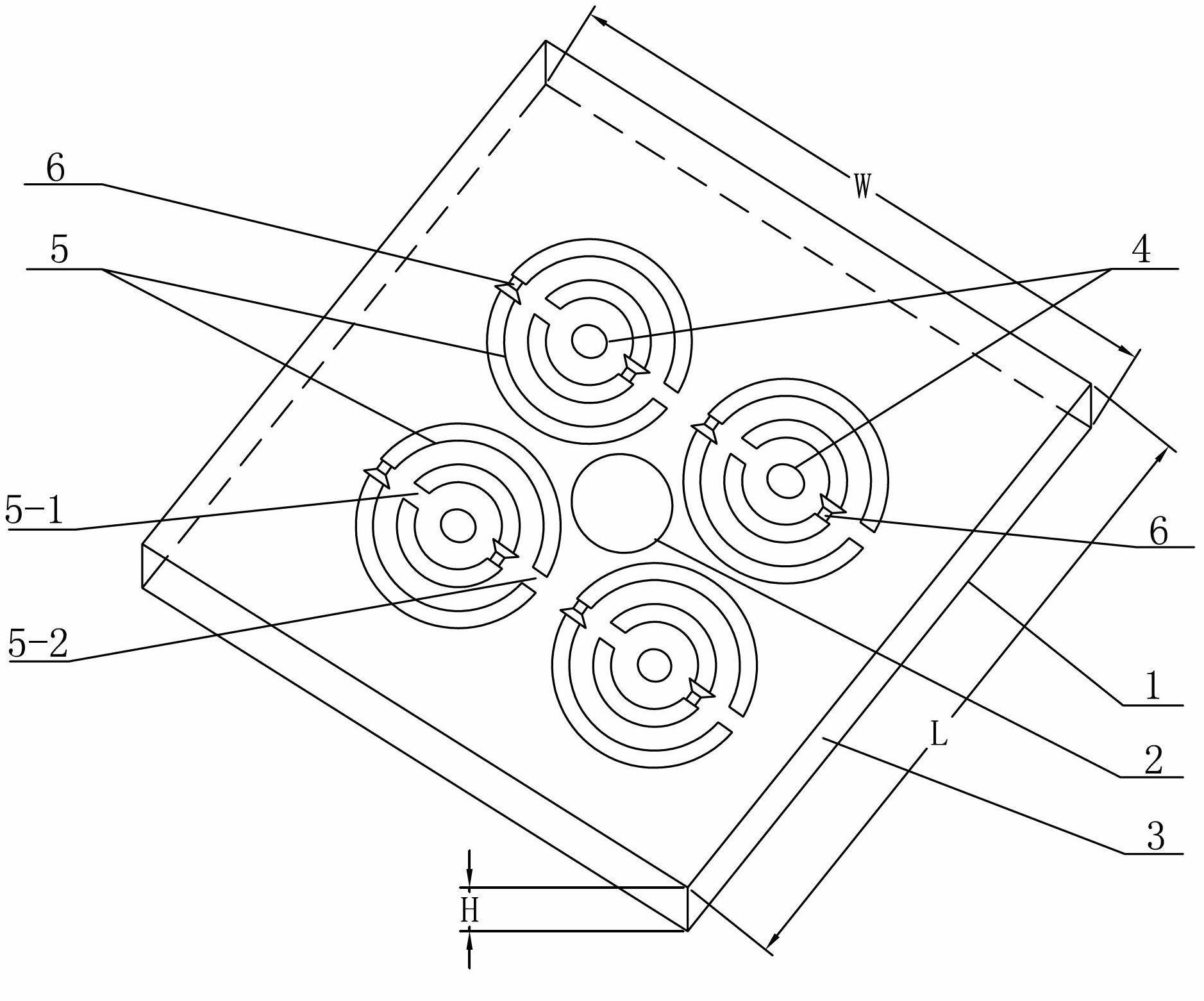
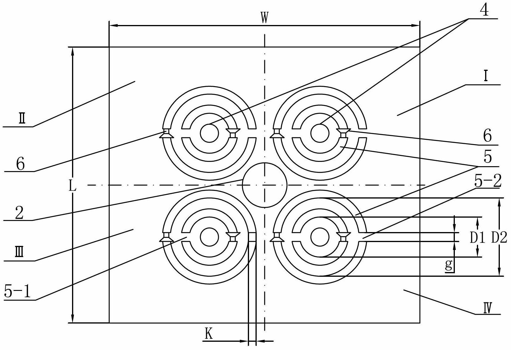
[0011] Specific implementation mode one: combine figure 1 and figure 2 To illustrate this embodiment, the multi-frequency pattern reconfigurable antenna based on double split resonator rings in this embodiment includes a first metal sheet 1, a round metal feeding sheet 2, a dielectric plate 3, four second metal sheets 4, Four metal split resonant rings 5 ​​and eight switches 6, a layer of metal sheet 1 is attached to the lower surface of the dielectric board 3, a circular metal feed sheet 2 is attached to the middle of the upper surface of the dielectric board 3, and the four metal split resonant rings 5 arrays are attached around the circular metal feeding sheet 2, and each metal split resonator ring 5 is a circular concentric inner and outer double-ring structure, and a second metal sheet 4 is attached to the center of each metal split resonator ring 5 , the inner ring of each metal split resonant ring 5 has two inner ring openings 5-1, the outer ring of each metal split r...

specific Embodiment approach 2

[0013] Specific implementation mode two: combination figure 2 To illustrate this embodiment, the inner ring inscribed circle diameter D1 of each metal split resonator ring 5 in this embodiment is 1mm-3mm, the outer ring inscribed circle diameter D2 is 3mm-5mm, the line width K is 1mm-2mm, and the opening The distance g is 0.8mm-1.2mm, and the thickness of the resonance ring is 0.03mm-0.04mm. Such setting meets the design requirements and actual needs. Others are the same as in the first embodiment.

specific Embodiment approach 3

[0014] Specific implementation mode three: combination figure 2 This embodiment is described. The dielectric plate 3 in this embodiment is a square dielectric plate, which is set up in this way to meet the design requirements and actual needs. Others are the same as in the first embodiment.


PUM


Abstract

The invention discloses a multifrequency directional-diagram reconfigurable antenna based on double-open resonant ring, relates to an antenna, and specifically relates to a directional-diagram reconfigurable antenna so as to solve the problem that the existing reconfigurable antenna is complex in structure and can not operate simultaneously at multiple different operating frequencies. The reconfigurable antenna comprises a first metal sheet, a round metal-form feed wafer, a dielectric slab, four second metal sheets, four metal open resonant rings and eight switches, wherein a layer of metal sheets is attached to the lower surface of the dielectric slab, the round metal-form feed wafer is attached to the middle part of the upper surface of the dielectric slab, the four metal open resonant rings are arrayed around and attached to the periphery of the round metal-form feed wafer, each metal open resonant ring is of a circular concentric inside-outside dual-ring structure, and the opening of one inner ring of each metal open resonant ring is provided with a switch. The multifrequency directional-diagram reconfigurable antenna based on double-open resonant ring is applied to wireless communication systems.

Description

technical field [0001] The invention relates to an antenna, in particular to an antenna with a reconfigurable pattern. Background technique [0002] As a component used to transmit or receive radio waves, the antenna plays a pivotal role in the wireless communication system and is an indispensable part of the wireless communication system. With the rapid development of high-frequency satellite communication systems, radar, wireless communication systems, especially the construction of global 3G and 4G networks, the requirements for antennas are getting higher and higher. On the one hand, the antenna needs to be able to work in multiple frequency bands, have multiple working modes and have good transmission performance. On the other hand, it is necessary to reduce the weight of the antenna, reduce the volume of the antenna and reduce the cost. The main function of the antenna is divided into two aspects: on the one hand, the antenna can convert energy; on the other hand, th...

Claims


Application Information

Patent Timeline
Patent Type & Authority Applications(China)
IPC IPC(8): H01Q25/00H01Q1/38H01Q3/24H01Q5/01H01Q9/04H01Q5/10
Inventor 华军陈美良唐卓黄帅孟繁义傅佳辉吴群
Owner 36TH RES INST OF CETC
Why Eureka
Try Eureka