
Distributed computer interlock control system for station signal and integration method thereof

A technology of computer interlocking and control systems, applied in the interlocking devices between turnouts and signals, railway signals, railway signals and safety, etc., can solve problems such as software errors and defects, waste of wires and cables, and difficulty, and achieve reduction Effects of scale and complexity, improvement of production efficiency, and improvement of reliability

Inactive Publication Date: 2009-03-25
BEIJING JIAOTONG UNIV
View PDF0 Cites 16 Cited by
  • Summary
  • Abstract
  • Description
  • Claims
  • Application Information

AI Technical Summary

Problems solved by technology

There are the following problems: centralized electrical interlocking based on wiring, a huge amount of intricate wiring, which makes system design, processing and troubleshooting construction errors very difficult, the efficiency of system processing and production is very low, and a lot of wires and cables are wasted; the basic units are tightly packed Coupling, a huge amount of wiring is intricate, causing the system to pull the whole body. Even if the station system undergoes a small partial reconstruction and expansion, the system and its wiring will be greatly changed, and even the overall design, production and construction will need to be re-designed.
These data sheets affect the whole body, and it is difficult to troubleshoot errors, which brings serious uncertainties to the reliability and safety of the interlocking system.
[0005] (2) The centralized interlocking mode requires computer interlocking software modules to centrally process a large number of complex and tightly coupled data tables of complete station signal equipment and their interrelationships, resulting in complex logical relationships between software modules that implement centralized interlocking functions , which increases the difficulty of software testing and safety assessment and certification, which may cause serious errors and defects in the software, seriously affecting the safety, reliability and usability of the interlocking software
[0006] (3) For the vastly different railway stations, the system manufacturer or integrator must establish a large number of data sheets that describe the complete station signal equipment and their interrelationships, and complete the system installation, commissioning, system reconstruction and expansion, and even system maintenance. This leads to long periods of time for system processing, production, testing, installation and commissioning, and low efficiency, which seriously affects the progress of large-scale promotion and application of the system and replacement.

Method used


Image

  • Distributed computer interlock control system for station signal and integration method thereof
  • Distributed computer interlock control system for station signal and integration method thereof

Examples


Embodiment 1

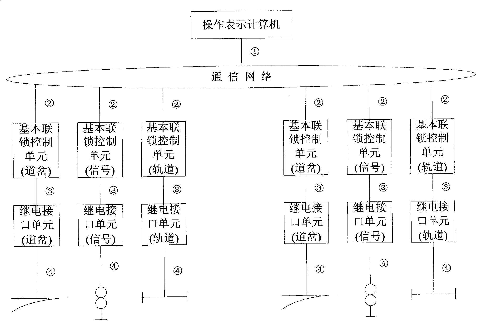
[0028] Embodiment 1: as figure 1 As shown, the station signal distributed computer interlocking control system consists of four layers: the human-computer interaction layer, which realizes the operation display function, and the equipment is placed in the operator room of the signal building; the interlocking layer, which is built with the basic interlocking control unit, Realize the interlocking calculation function, the unit is placed in the mechanical room of the signal building; the outdoor equipment measurement and control drive interface layer is built with safety relays, and this layer is placed in the mechanical room of the signal building; the outdoor equipment layer, this layer is the outdoor signal machine, turnout And track circuit and other equipment.

[0029] The human-computer interaction layer and the interlocking layer are connected through a redundant wired or wireless communication network ①; the interlocking layer is connected through a redundant wired comm...

Embodiment 2

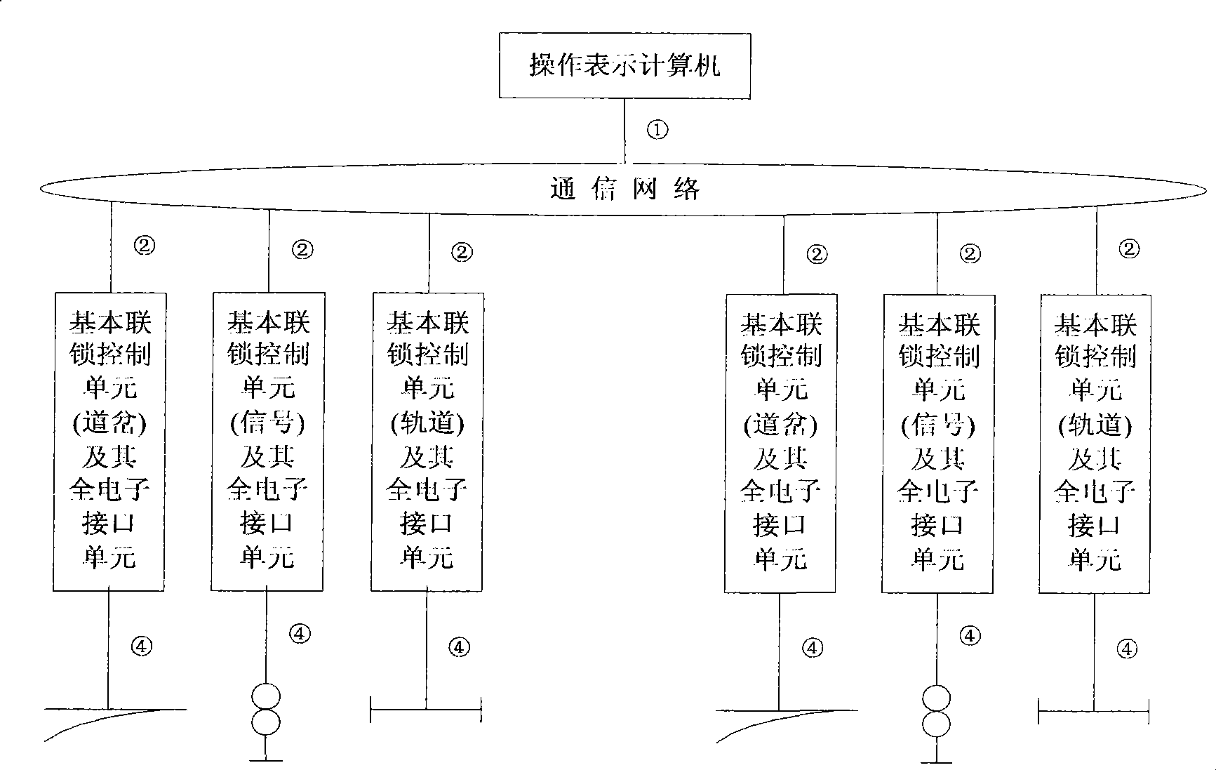
[0030] Embodiment 2: as figure 2 As shown, in this embodiment, the outdoor equipment measurement and control drive interface layer adopts a fully electronic module, and can be selected to be combined with the corresponding basic interlocking control unit; in this embodiment, the station signal distributed computer interlocking control The system has a three-layer structure: the human-computer interaction layer, which realizes the operation display function, and the equipment is placed in the operator's room of the signal building; the interlock layer, which is composed of the basic interlock control unit and its fully electronic outdoor equipment measurement and control drive interface layer. , to realize the interlocking calculation function and have the measurement and control driving function of outdoor equipment. The interlocking layer can be installed in the mechanical room of the signal building, and can also be installed next to outdoor equipment such as signal machines...


PUM


Abstract

The invention relates to a station signal distributed computer interlocking control system which is composed of a human-computer interaction layer for realizing the operation expression function, a distributed interlocking layer for realizing the interlocking calculation function, an outdoor device measurement and control driving interface layer for realizing the measurement and control driving function of a trackside device and an outdoor device (a trackside semaphore, a turnout, a track circuit and the like). The distributed interlocking layer of the system does not adopt the centralized interlocking calculation mode, distributes the interlocking logic calculation into each basic interlocking control unit which is corresponding to a special field device (such as the semaphore, the turnout and the rail circuit), and the interlocking control process of the station signal is jointly completed by a group of basic interlocking control units. The distributed computer interlocking control which is realized by the invention can greatly improve the reliability, the safety and the availability of the station signal computer interlocking control system.

Description

technical field [0001] The invention relates to a rail transit operation control system, in particular to a station signal distributed computer interlocking control system and an integration method thereof. Background technique [0002] The station signal interlocking control system is a command control and safety protection system that directs the train to complete the technical operations in the station and ensures its safe operation. At present, there are two types of control systems that realize this function at home and abroad. One is the station signal electrical centralized interlocking control system based on wiring logic that appeared in the 1960s with relays as the basic components. There are the following problems: centralized electrical interlocking based on wiring, a huge amount of intricate wiring, which makes system design, processing and troubleshooting construction errors very difficult, the efficiency of system processing and production is very low, and a l...

Claims


Application Information

Patent Timeline
IPC IPC(8): B61L19/00
Inventor 徐洪泽郑伟刘湘黔
Owner BEIJING JIAOTONG UNIV
Learn More