
Micro vortex flow tube arrangement method of recycle hydrogen de-hydrocarbon machine

A technology of a hydrodehydrocarbonizer and an arrangement method, which is applied in the field of swirling tube arrangement, can solve the problems of increasing equipment consumables and the like

Active Publication Date: 2009-03-25
SHANGHAI HUACHANG ENVIRONMENT PROTECTION
View PDF1 Cites 5 Cited by
  • Summary
  • Abstract
  • Description
  • Claims
  • Application Information

AI Technical Summary

Problems solved by technology

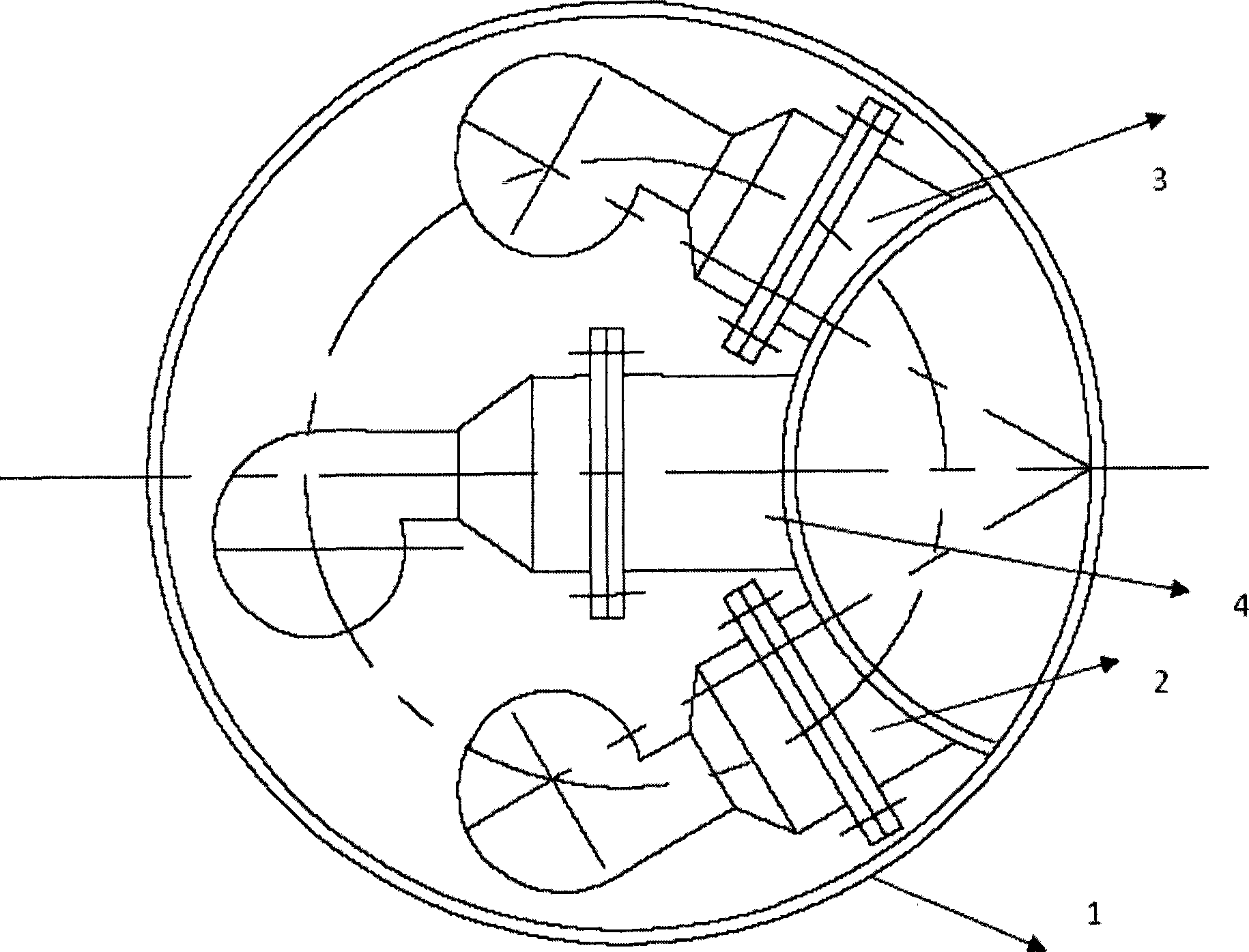
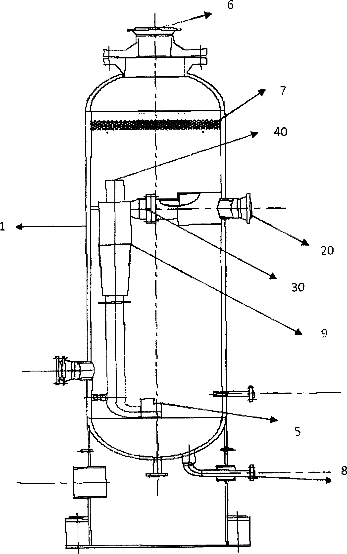
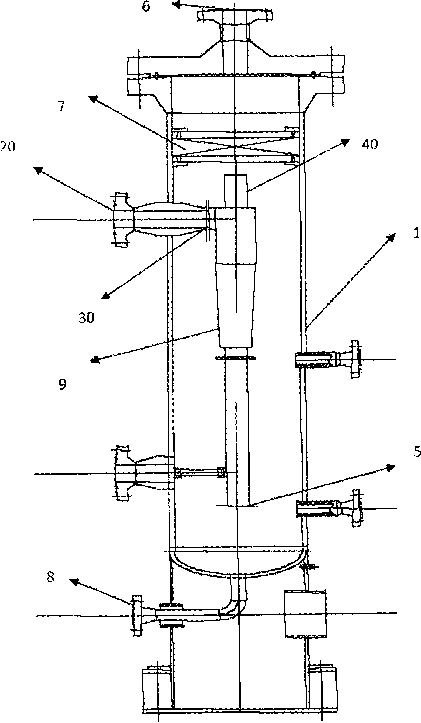
The primary technical problem to be solved by the present invention is to solve the problem of increasing equipment consumables in the existing cyclone separator with sub-chambers, improve the overall layout of the swirl core tube group, and provide a micro-cyclone tube for a circulating hydrodecarbonizer. Layout method

Method used


Image

  • Micro vortex flow tube arrangement method of recycle hydrogen de-hydrocarbon machine
  • Micro vortex flow tube arrangement method of recycle hydrogen de-hydrocarbon machine
  • Micro vortex flow tube arrangement method of recycle hydrogen de-hydrocarbon machine

Examples


Embodiment Construction

[0023] After extensive and in-depth research, the inventors of the present invention found that the separation time of the circulating hydrogen mixture can be reduced by collecting all the inlets of the micro-swirl tube or the group of micro-swirl tubes and sealingly connecting them with the inlet pipe of the pressure vessel , the cancellation of the sub-chamber tube sheet in the original cyclone can effectively reduce the investment cost of the decarburizer steel and shorten the equipment processing cycle. In addition, the equilateral triangle arrangement of the micro-swirl tube group makes the interior of the equipment more compact, and at the same time Improved device stability. The present invention has been accomplished based on the above findings.

[0024] Technical conception of the present invention is as follows:

[0025] The circulating hydrodecarburizer cancels the tube sheet in the original cyclone, and the mixed gas enters the cyclone tube directly from the inlet...


PUM


Abstract

The invention relates to an arranging method of a micro swirl tube used for a cycle-hydrogen hydrocarbon remover and a corresponding apparatus, and provides an arranging method of the micro swirl tube used for the cycle-hydrogen hydrocarbon remover. The method includes the following steps: the inlets of the micro swirl tube of the micro tube units in the cycle-hydrogen hydrocarbon remover are collected and are connected in a sealed manner with the inlet of a pressure container of the recycle-hydrogen hydrocarbon remover. The invention also provides a cycle-hydrogen hydrocarbon remover apparatus.

Description

technical field [0001] The invention relates to a method for arranging swirl tubes of a circulating hydrodecarbonizer, in particular to a method for arranging micro-swirl tubes or groups of micro-swirl tubes of a circulating hydrodecarburizer of a hydrogenation device. The invention also relates to a recycle hydrodecarburizer unit. Background technique [0002] In a hydrocracking unit, the circulating hydrogen carries hydrocarbons, especially entrained C 5 、C 6 、C 7 Heavy hydrocarbons above and above will easily cause foaming of the desulfurization tower, increase the operating load of the desulfurization tower, threaten the safety and long-term stable operation of the circulating hydrogen compressor, increase the molecular weight of circulating hydrogen, reduce the purity of hydrogen, and bring great harm to the downstream system. Harm, shorten the service life of the catalyst and the efficiency of the reaction. Therefore, the entrainment of heavy hydrocarbons by circul...

Claims


Application Information

Patent Timeline
IPC IPC(8): C01B3/50
Inventor 马吉汪华林徐效梅钱卓群罗凤崔馨杨强
Owner SHANGHAI HUACHANG ENVIRONMENT PROTECTION
Learn More