Medium temperature glass-metal structure solar vacuum thermal-collecting tube

A technology of vacuum heat collecting tube and metal structure, which is applied in the field of solar energy utilization, and can solve problems such as peeling off of copper oxide skin, affecting the heat collection effect of heat collecting tube, and oxidation of copper surface

Inactive Publication Date: 2009-03-25
TSINGHUA UNIV
View PDF0 Cites 35 Cited by
  • Summary
  • Abstract
  • Description
  • Claims
  • Application Information

AI Technical Summary

Problems solved by technology

[0002] The glass-metal structure solar vacuum heat collection tube formed by installing the heat transfer tube with heat conduction fins in the existing all-glass vacuum solar heat collection tube is to solve the low-temperature heating of the all-glass vacuum solar heat collection tube in cold regions. To obtain a good heat conduction effect, the heat transfer tube with heat transfer fins uses copper as raw material, and the obtained temperature is generally below 85°C; since the heat transfer tube with heat transfer fins works in the air, the temperature will reach above 100°C under air drying conditions, and the long-term Use will cause serious oxidation of the copper surface, and even the copper oxide skin will fall off, which will greatly affect the heat collection effect of the heat collector tube.

Method used


Image

  • Medium temperature glass-metal structure solar vacuum thermal-collecting tube
  • Medium temperature glass-metal structure solar vacuum thermal-collecting tube
  • Medium temperature glass-metal structure solar vacuum thermal-collecting tube

Examples


Embodiment Construction

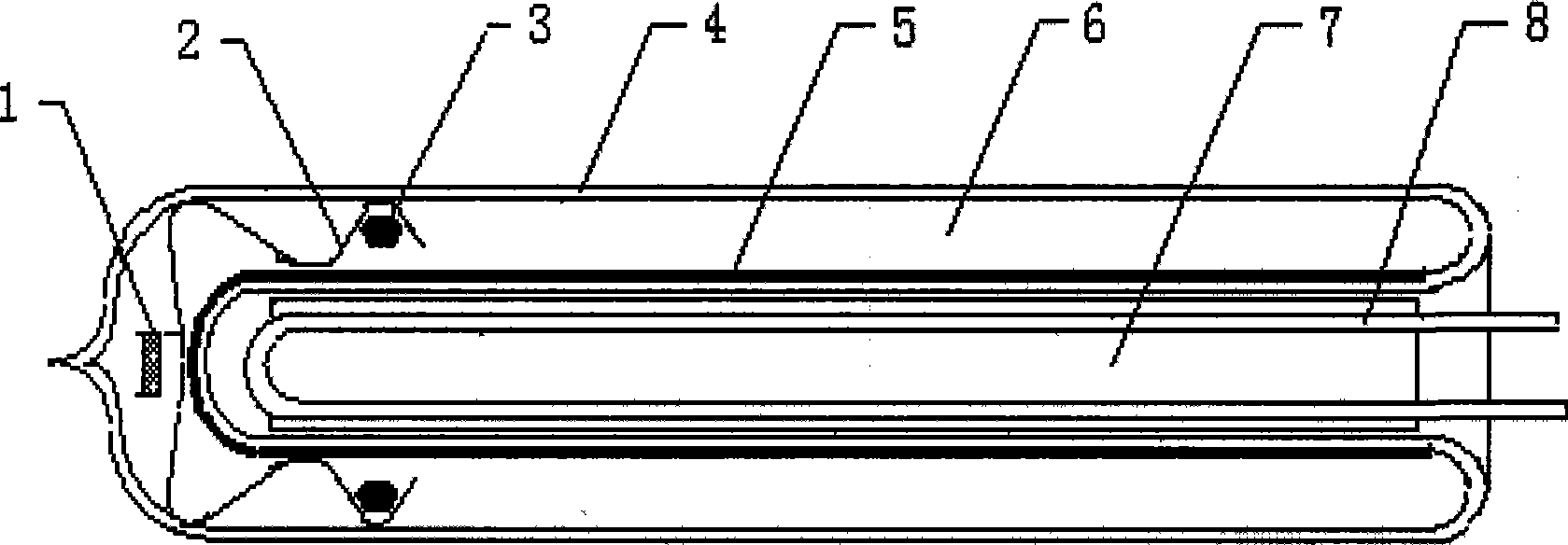
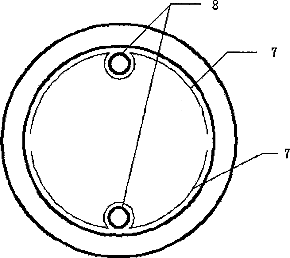
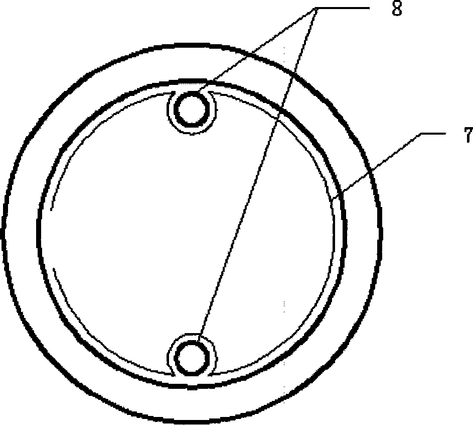
[0015] The invention proposes a solar vacuum heat collecting tube with a medium temperature glass-metal structure. Structure Fig. 1 is a kind of novel mid-temperature glass-metal solar vacuum heat collecting tube (U-shaped copper tube structure) structure schematic diagram of the present invention and Fig. 2 is a kind of novel medium temperature glass-metal solar vacuum heat collecting tube (copper tube) of the present invention Heat pipe structure) Schematic diagram of the structure.

[0016] In Fig. 1, the heat transfer tube 8 with a temperature-resistant and anti-oxidation film is tightly crimped or welded on the heat conduction fin 7, the inner glass heat collector tube 5 with a selective absorption film, the heat conduction fin 7 and the all-glass vacuum solar collector The inner walls of the heat pipe 4 are in close contact. The non-evaporable getter 3 is fixed on both sides of the metal support 2, the evaporable getter 1 is fixed on the top of the metal support 2, the ...


PUM

PropertyMeasurementUnit
thermal resistanceaaaaaaaaaa

Abstract

The invention discloses an intermediate temperature glass-metallic structure solar vacuum thermal-collecting tube, which belongs to the technical field of solar utilization, wherein a layer of temperature-resistant anti-oxidation film is plated on the outer surface of a heat-transfer pipe provided with a heat-conductive wing in the intermediate temperature glass-metallic solar vacuum thermal-collecting tube, and the film layer is aluminum or zinc or nickel or chromium or stainless steel; the heat-conductive wing is a thin aluminum plate which is coiled into the shape of an opening cylinder or a semicircular cylinder, and is tightly connected or welded with a U-shaped copper tube or a copper heat pipe of the temperature-resistant anti-oxidation film; and a heat-conductive wing tube is arranged inside the all-glass solar vacuum thermal-collecting tube, and closely contacts the inner wall of the all-glass solar vacuum thermal-collecting tube. A non-evaporable getter can be arranged inside a vacuum interlayer of the all-glass solar vacuum thermal-collecting tube, thereby improving the vacuum service life of the all-glass solar vacuum thermal-collecting tube after the long-term operating temperature is extended to more than 140 DEG C. The invention is a novel intermediate temperature glass-metallic solar vacuum thermal-collecting tube with high cost performance, and can meet the requirements of solar air-conditioners and industrial heat.

Description

technical field [0001] The invention belongs to the technical field of solar energy utilization, and in particular relates to a novel solar vacuum heat collecting tube with a medium temperature glass-metal structure for meeting the requirements of solar air conditioning and industrial heating. technical background [0002] The glass-metal structure solar vacuum heat collection tube formed by installing the heat transfer tube with heat conduction fins in the existing all-glass vacuum solar heat collection tube is to solve the low-temperature heating of the all-glass vacuum solar heat collection tube in cold regions. To obtain a good heat conduction effect, the heat transfer tube with heat transfer fins uses copper as raw material, and the obtained temperature is generally below 85°C; since the heat transfer tube with heat transfer fins works in the air, the temperature will reach above 100°C under air drying conditions, and the long-term Use will cause serious oxidation of th...

Claims


Application Information

Patent Timeline
Patent Type & Authority Applications(China)
IPC IPC(8): F24J2/05F24J2/24F24S10/40F24S10/70
CPCY02E10/44F24J2/485F24J2/4616F24J2/055F24S10/45F24S10/75F24S40/46F24S70/20Y02P80/20
Inventor 齐京殷志强王健高元坤
Owner TSINGHUA UNIV
Why Eureka
Try Eureka