
Temperature control device for on-board battery pack

A technology for temperature control devices and battery packs, applied in battery temperature control, temperature control without auxiliary power supply, battery/fuel cell control devices, etc., can solve the problems of poor fuel combustion efficiency and increased fuel consumption, and achieve The effect of increased heat transfer rate and rapid temperature

Active Publication Date: 2009-04-01
DENSO CORP
View PDF1 Cites 36 Cited by
  • Summary
  • Abstract
  • Description
  • Claims
  • Application Information

AI Technical Summary

Problems solved by technology

However, although the battery pack can be warmed up quickly and uniformly, the electric power of the battery pack is only used to warm up the battery pack
Therefore, the amount of fuel consumption is undesirably increased so that the fuel consumption efficiency of the vehicle deteriorates

Method used


Image

  • Temperature control device for on-board battery pack
  • Temperature control device for on-board battery pack
  • Temperature control device for on-board battery pack

Examples


Embodiment 1

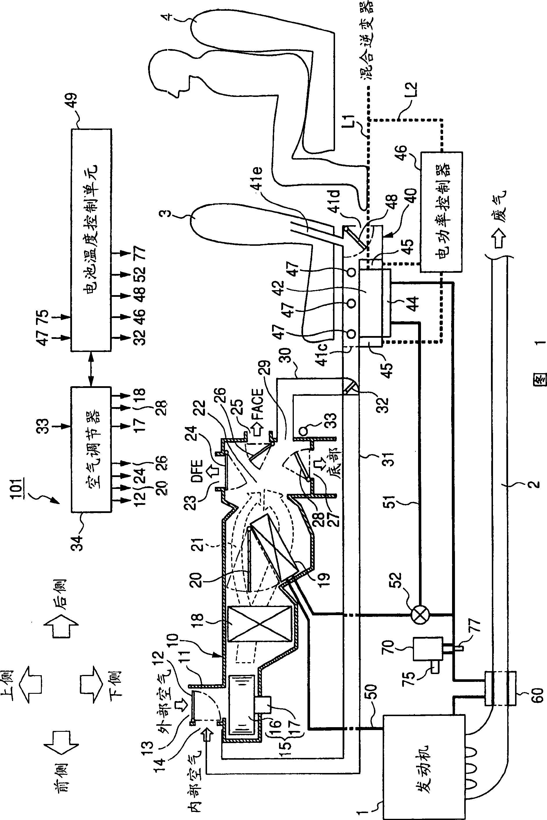
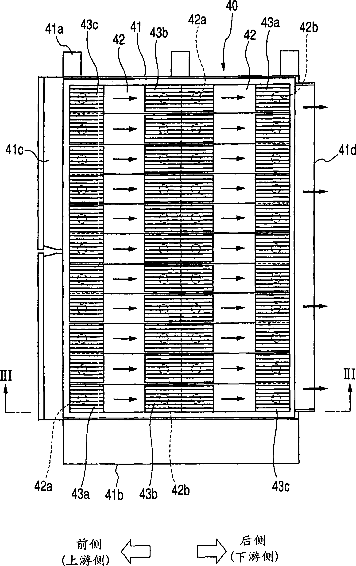
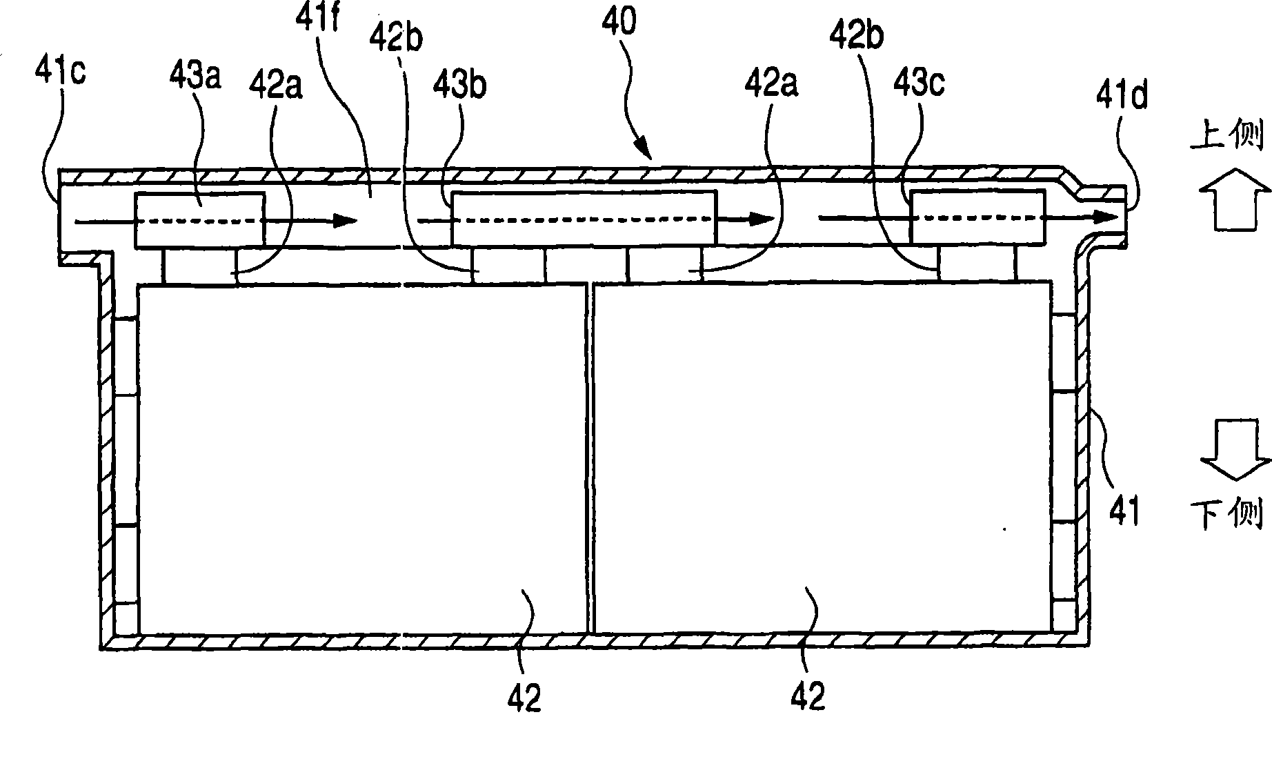
[0030] FIG. 1 is a schematic diagram of a temperature control device for an on-vehicle battery pack according to a first embodiment. The temperature control device 101 shown in FIG. 1 is mounted, for example, on a hybrid vehicle having a water-cooled internal combustion engine 1 and an electric motor (not shown) as a driving power source. The electric motor receives electric power from the on-board battery pack 40 to cooperate with the engine 1 to move the locomotive. The temperature control device 101 is used to heat the battery pack 40 or to cool the battery pack.

[0031] As shown in Figure 1, the temperature control device 101 has an air conditioner 10, an air duct (airduct) 30, and a hot water heater (or fluid heating element) 44, and the air conditioner 10 is used to adjust the temperature of the air to generate a temperature The controlled air blows a part of the controlled air to the compartment, and the remaining part of the controlled air is guided to the battery pa...

Embodiment 2

[0103] FIG. 7 is a schematic diagram of a temperature control device for the battery pack 40 according to the second embodiment.

[0104] As shown in FIG. 7 , the temperature control device 102 has a heat-cooling water circulation system different from that of the device 101 shown in FIG. 1 . Specifically, the circulation system of the control device 102 has a circulation channel 50, a first heat exchanger 60A, a heat storage tank 70, a fluid circulation channel 53 filled with brine, a fluid pump 54, a fluid temperature sensor 55, and a second heat exchanger 60B. , the circulation channel 50 communicates with the engine 1 and the heater core 19 . The first heat exchanger 60A is for recovering the heat of the exhaust gas of the engine 1 flowing through the exhaust pipe 2 and transferring the recovered heat to the cooling water of the channel 50 so that the hot cooling water circulates in the channel 50; the fluid pump 54 Operate under the control of the control unit 49 to circ...


PUM


Abstract

A temperature control device has a heat exchanger recovering heat from exhaust gas of an engine, a water circulating passage in which a cooling water is circulated while receiving the recovered heat, an air conditioning unit heating air with the hot cooling water of the passage to produce a temperature controlled air, an air duct, a water heater attached to the bottom surface of a battery pack, and an electric heater attached side surfaces of the pack. The conditioning unit blows the controlled air against the battery pack through the duct. The water heater receives the hot cooling water of the passage and raises the temperature of the battery pack. The electric heater subsidiarily warms the battery pack with heat generated from electric power of the pack.

Description

technical field [0001] The present invention relates to a temperature control device for adjusting the temperature of a battery pack mounted on a vehicle. Background technique [0002] A battery temperature control device for adjusting the temperature of a battery pack mounted on a vehicle is disclosed in published Japanese Patent First Publication No. 2004-1674. In this device, in order to prevent the temperature of the battery pack from being excessively high, the temperature of the air is adjusted at the air control unit, from which temperature-controlled air (hereinafter, referred to as controlled air) is introduced to the battery through ducts. The group is used to adjust the temperature of the battery pack. Therefore, the control unit can prevent the temperature of the battery pack from being excessively high so that the battery pack does not degrade. [0003] Conversely, when the temperature of the battery pack is too low, it is necessary to increase the temperature...

Claims


Application Information

Patent Timeline
Patent Type & Authority Applications(China)
IPC IPC(8): B60H1/00G05D23/01G05D23/20B60H1/08B60H1/22B60K1/04B60K11/04H01M10/60H01M10/613H01M10/615H01M10/625H01M10/6551H01M10/6556H01M10/6563H01M10/6571H01M10/663
CPCB60H1/00492B60H1/00278H01M10/5004H01M10/5016G05D23/1932H01M10/486H01M10/5067H01M10/5006H01M10/5073B60H2001/003H01M10/5095H01M10/5077B60H1/025H01M10/625H01M10/615H01M10/663H01M10/6563H01M10/6568H01M10/6566H01M10/613B60L1/003B60L1/02B60L2240/34B60L2240/36B60L2240/445B60L2240/545B60L50/15B60L58/26B60L58/27B60L50/66B60L50/64B60H1/00499Y02T10/70Y02T10/7072Y02E60/10B60L3/0046
Inventor 田村博志坂鉱一
Owner DENSO CORP
Learn More