Switched reluctance motor device with high voltage and large power

A high-power switch, reluctance motor technology, applied in electromechanical devices, stop devices, AC motor control, etc., can solve problems such as easy failure, increase, and user inconvenience

Inactive Publication Date: 2009-04-01
BEIJING CHINA TEX MECHANICAL & ELECTRICAL ENG
View PDF0 Cites 1 Cited by
  • Summary
  • Abstract
  • Description
  • Claims
  • Application Information

AI Technical Summary

Problems solved by technology

However, the increase in the connection or ratio between the motor and the controller brings inconvenience to the user and is also prone to failure; in addition, the number of coils of the motor phase winding is not large, and the power of the switched reluctance motor device can only be increased by a limited multiple

Method used


Image

  • Switched reluctance motor device with high voltage and large power
  • Switched reluctance motor device with high voltage and large power
  • Switched reluctance motor device with high voltage and large power

Examples


Embodiment 1

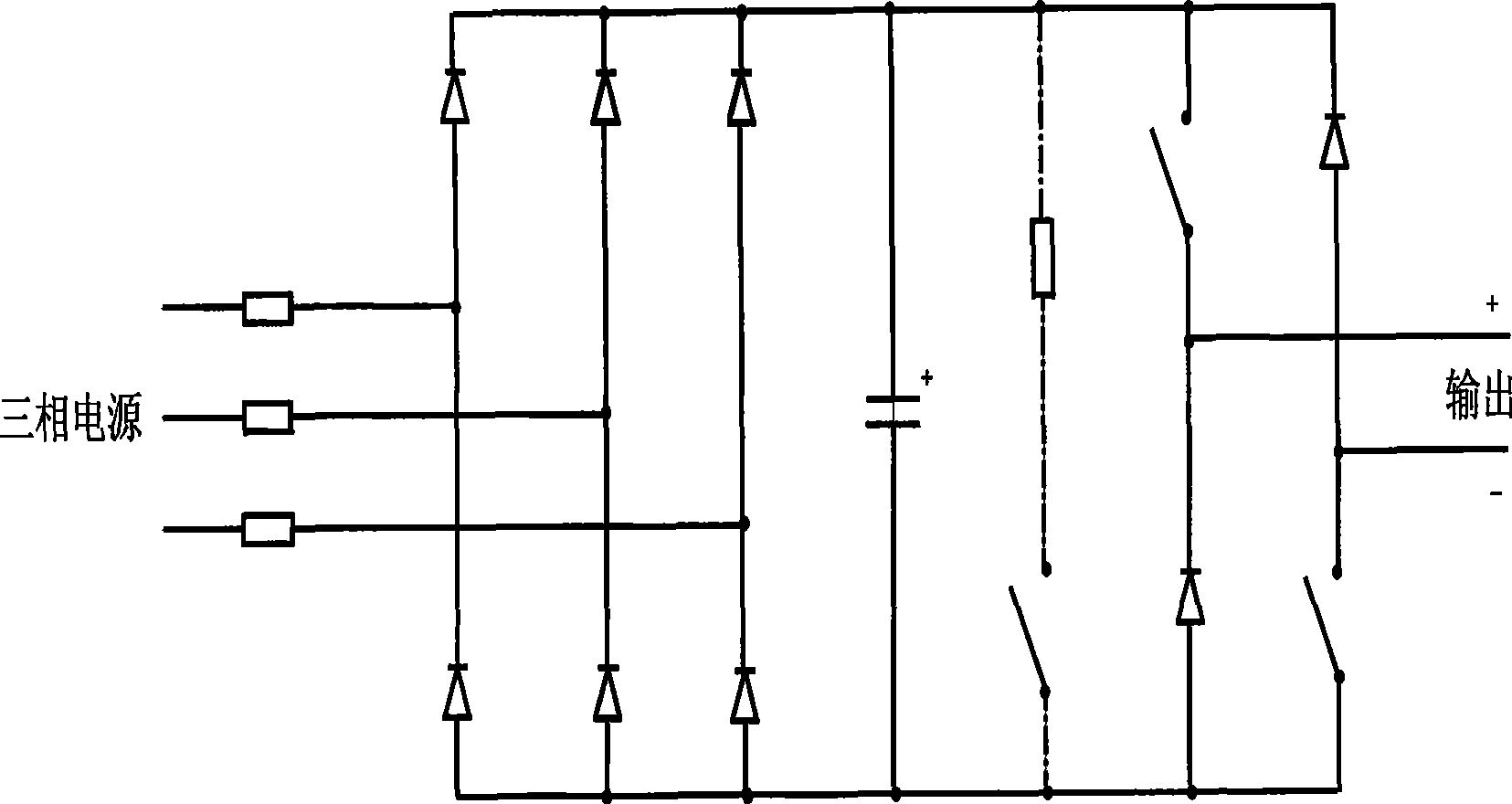
[0036] image 3 The common power unit used in the present invention mainly includes a three-phase bridge rectifier circuit, a filter capacitor and a single-phase half-bridge inverter circuit. The dotted line in the figure shows the voltage-limiting discharge circuit, which can be set when necessary.

[0037] The single-phase inverter circuit is composed of a positive bridge arm and a negative bridge arm. Both bridge arms are connected in series with power switches and freewheeling diodes, and the connection between the two is used as the output terminal. Positive bridge arm, one end of the power switch is connected to the positive end of the power supply, and the output end is positive. Negative bridge arm, one end of the power switch is connected to the negative end of the power supply, and the output end is negative.

[0038]In the three-phase bridge rectifier circuit, the six rectifier diodes used are all connected in parallel with power switches to form a feedback power ...

Embodiment 2

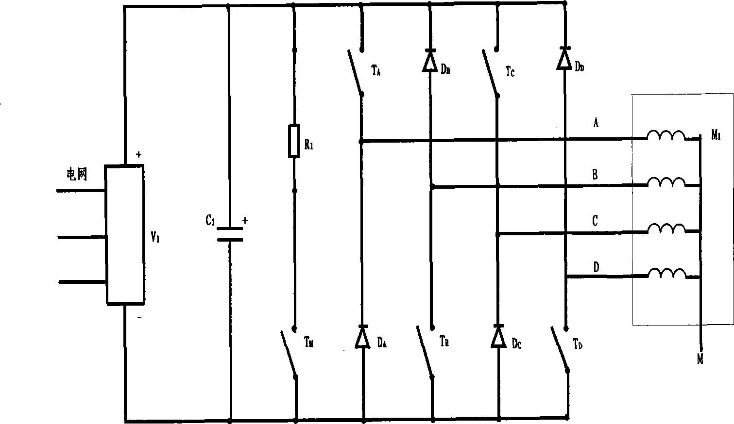
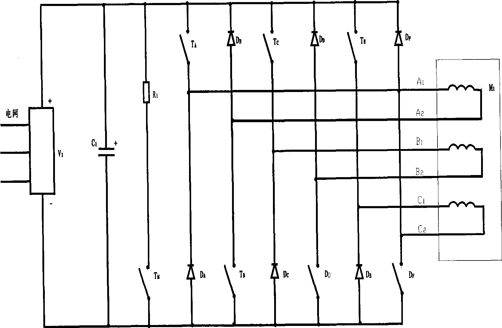
[0046] The switched reluctance motor device described in the present invention has a wider application range and can be used when the number of phases is odd or even. Its N-phase windings themselves are mutually insulated, and there is no common connection point. It has its own independent current loop. The number of outgoing wires of the motor is 2N.

[0047] Taking a 3-phase switched reluctance motor as an example, Figure 5 When Z=3, the present invention of the three-phase switched reluctance motor shares N·Z=9 power units. The outputs of UA1, UA2 and UA3 are connected in series to drive the A-phase winding, the outputs of UB1, UB2 and UB3 are connected in series to drive the B-phase winding, and the outputs of UC1, UC2 and UC3 are connected in series to drive the C-phase winding.

[0048] exist Figure 5 The secondary side winding adopts delta connection and delta connection with extended side. #1, #2 and #3 supply power to A, B and C three-phase windings. The connecti...


PUM


Abstract

The invention provides a high-voltage high-power switch reluctance motor device. The device comprises an N-phase high-voltage high-power switch reluctance motor, a power unit and a phase-shifting transformer (T1); and Z power unit outputs are arranged in direct series corresponding to each phase winding of the switch reluctance motor; the switch reluctance motor device comprises Z*N power units, and three-phase electric source of the Z*N power units is provided by the secondary winding of the phase-shifting transformer. The number of the wires of the device of the invention is small, operation is reliable, and power is improved by a plurality of times.

Description

technical field [0001] The invention relates to a switched reluctance motor device, in particular to a high-voltage and high-power switched reluctance motor device output by multiple power units directly connected in series. Background technique [0002] In recent years, switched reluctance motor devices have been more and more widely used, and the required power is increasing. The system consists of two parts, the motor and the controller, and there are many structural forms of the motor, and the commonly used forms are 4-phase 8 / 6 poles, 3-phase 12 / 8 poles, etc. [0003] After omitting the power-on current limiting circuit, the main circuit of the current 4-phase switched reluctance motor is as follows: figure 1 shown. Three-phase power grid input, after bridge rectification and capacitor filtering, a DC power supply is obtained; 4 bridge arms composed of power switches and freewheeling diodes in series form a half-bridge power inverter circuit, which is provided to the ...

Claims


Application Information

Patent Timeline
Patent Type & Authority Applications(China)
IPC IPC(8): H02K29/00H02P6/08H02P6/24H02K11/33H02P25/08
Inventor 裘锦灼高超
Owner BEIJING CHINA TEX MECHANICAL & ELECTRICAL ENG
Why Eureka
Try Eureka