Split type multi-roller multi-component high-gradient vibration magnetic separator in permanent magnetism

A high-gradient, magnetic separator technology, applied in the direction of high-gradient magnetic separators, etc., can solve the problems of large consumption of materials, high requirements for equipment processing and manufacturing, and insufficient utilization of permanent magnet magnetic energy, and achieve the effect of increasing mechanical strength

Inactive Publication Date: 2009-04-08
HENAN POLYTECHNIC UNIV
View PDF2 Cites 30 Cited by
  • Summary
  • Abstract
  • Description
  • Claims
  • Application Information

AI Technical Summary

Problems solved by technology

[0011] In summary, although the current research on permanent magnet high-gradient magnetic separation technology has initially solved the problems of magnetic system structure, magnetic field strength, and blockage during the separation process, it has the conditions for initial application in industrial production, but in the actual application process There are still some outstanding problems in the following aspects: (1) The structure of the magnetic system is not reasonable, the field strength in the sorting area is low, and the magnetic energy of the permanent magnet is not fully utilized; (3) The sorting space is narrow, the equipment processing and manufacturing requirements are high, and the consumption of materials is large; (4) The magnetic field

Method used


Image

  • Split type multi-roller multi-component high-gradient vibration magnetic separator in permanent magnetism
  • Split type multi-roller multi-component high-gradient vibration magnetic separator in permanent magnetism
  • Split type multi-roller multi-component high-gradient vibration magnetic separator in permanent magnetism

Examples


Embodiment Construction

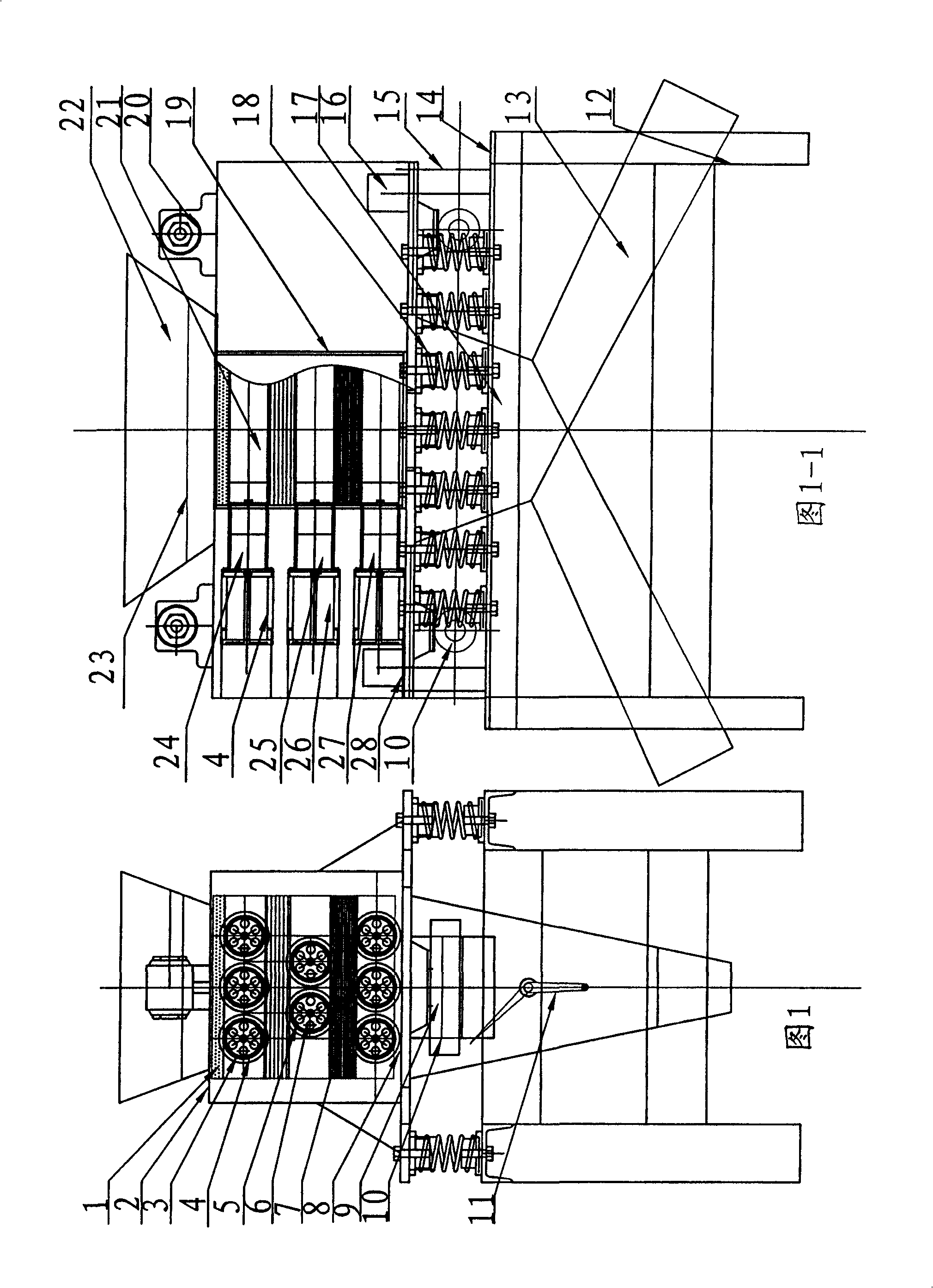
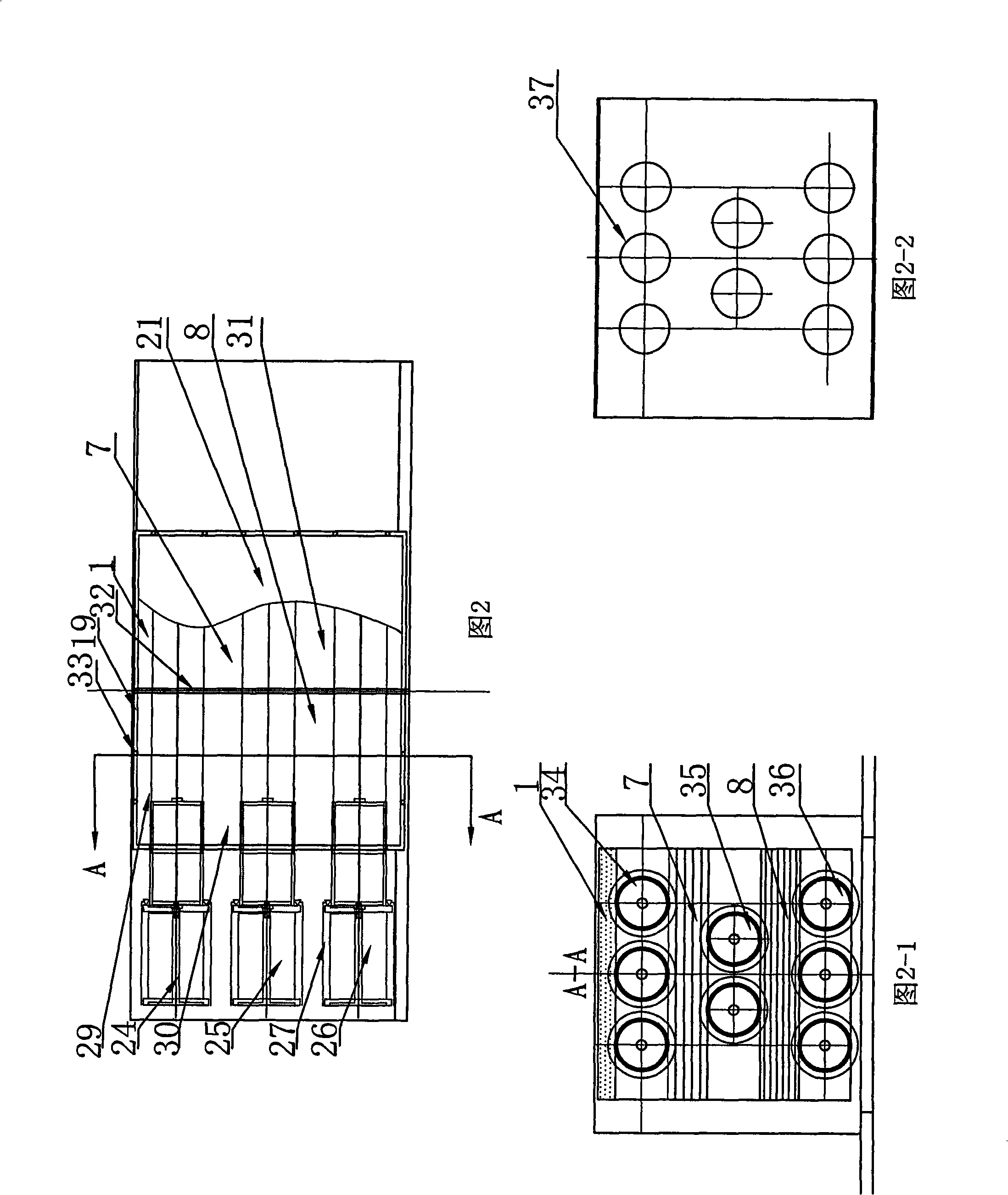
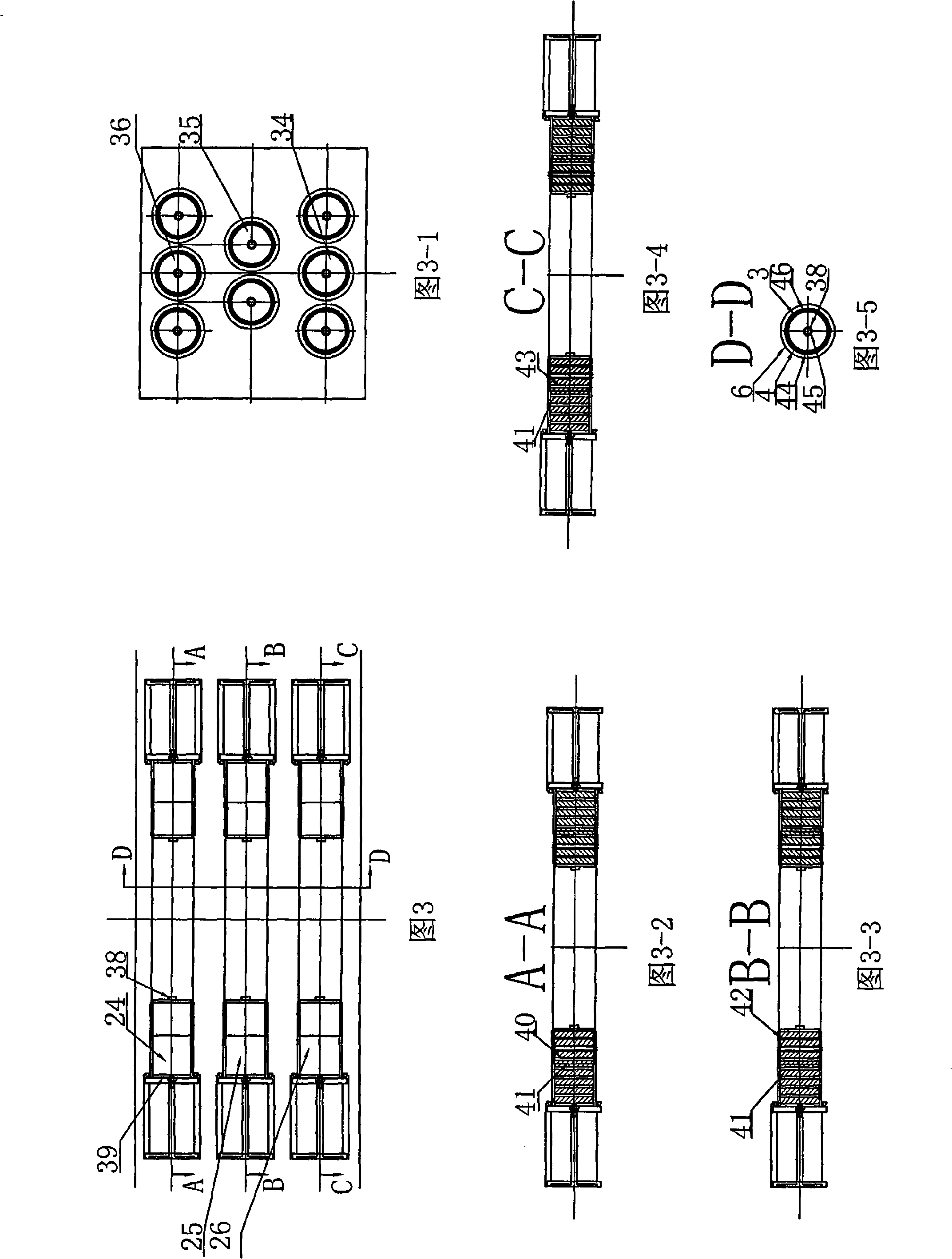
[0048] The present invention will be further described below in conjunction with embodiment (accompanying drawing):

[0049] As shown in Fig. 1 and Fig. 1-1. High gradient magnetic separator of the present invention comprises frame 12, is arranged on the body (magnetic separation box body) 2 that is made of upper and lower cover and side cover above frame 12, The body 2 is connected to the frame 12 through the damping spring group 18, and then installed above the frame 12 by bolts, and the cylinder installation area of ​​the air circuit 5 of the cylinder 4 is arranged on the side of the upper end of the frame 12 and the lower end of the body 2 9 and the pneumatic control group interface 14; the upper and lower parts of the body 2 are respectively equipped with a pneumatic vibrator 20 and a mechanical vibrator 10; And to make the feeding uniform, the lower part is installed with a discharge hopper, a discharge channel 17 and a material distribution plate 13, which is used to se...


PUM


Abstract

The invention relates to a permanent magnetic midsplit type multi-roller multivariate high gradient vibration magnetic selector, which comprises a stander (12), a magnetic selection box body arranged above the stander (12) through a vibration reduction spring set (18), a plurality of permanent magnetic rollers arranged inside the magnetic selection box body, a feed hopper (22) positioned on the top of the magnetic selection box body and a feed discharging passage (17) positioned on the bottom of the magnetic selection box body. The vibration magnetic selector is characterized in that the permanent magnetic rollers are made from magnetic materials with different magnetic strengths; according to a two-dimensional matrix form, the plurality of the permanent magnetic rollers are arranged to construct a multivariate sorting magnetic field; the permanent magnetic rollers made from the magnetic material of the same type are positioned on the same plane; according to the magnetic strengths, the permanent magnetic rollers with different magnetisms are in deltaic alternate arrangement sequentially from top to bottom along the flowing direction of the materials; magnetic concentrating medium grooves with the same specification are arranged between the adjacent permanent magnetic roller layers in different layers and above the upper layer of the permanent magnetic roller layers; and the inside of each groove is provided with magnetic concentrating media with different types.

Description

technical field [0001] The patent of the present invention relates to a magnetic separation device, in particular to a permanent magnet split-type multi-roller multi-element high-gradient vibration magnetic separator. This magnetic separator is suitable for processing wide-grained powder materials containing a variety of different magnetic minerals. It can be used for wet separation, dry separation, and industrial sewage treatment. Background technique [0002] Electromagnetic magnetic separator is still the mainstream equipment for strong magnetic separation. Since the electromagnet needs an excitation power supply and a cooling system is needed to solve the heating problem of the coil, a large amount of conductive copper bars or copper tubes and Electrician pure iron not only has complex equipment structure, inconvenient maintenance, high price, but also high operating cost, while the permanent magnet can provide a stable magnetic field after only one magnetization, and do...

Claims


Application Information

Patent Timeline
IPC IPC(8): B03C1/025
Inventor 焦红光刘鹏鲁富山铁占续马娇
Owner HENAN POLYTECHNIC UNIV
Why Eureka
Try Eureka