Nailing gun

A nailing gun and nailing technology, which is applied in the field of nailing guns, can solve the problems of inability to hit continuously, the structure is not compact, and the efficiency of pushing nails is low, and achieves the effect of outstanding substantive characteristics, compact structure, and continuous and efficient hitting.

Active Publication Date: 2009-04-15
NANJING CHERVON IND
View PDF3 Cites 5 Cited by
  • Summary
  • Abstract
  • Description
  • Claims
  • Application Information

AI Technical Summary

Problems solved by technology

The problem with this type of nail gun is that the slider crank mechanism cannot achieve real driving, and is essentially a "push" nail mechanism. Under the same motor power, the efficiency of pushing nails is much lower than that of driving. The efficiency of nails; the second is that during each nail pushing process, the crank slider mechanism must push the nail pushing element to travel the same stroke. When the nail encounters a hard object and the resistance is too large, it is easy to cause the motor to stall and cause the motor to be damaged. ; The third is that the motor is placed on the front or rear side of the handle, and it is connected with the transmission mechanism to occupy a large space, which makes the nail gun bulky and is not convenient to carry and operate.
Although this nail gun utilizes spring energy storage to realize instant hitting on nails, it can only be clicked one by one and cannot be hit continuously, and the hitting force generated only by the energy released by the spring is not high in efficiency, resulting in the nailing The gun is not suitable for regular use as a regular tool; in addition, its motor is located in the casing under the gun head, completely separated from the handle, and there is still the problem of not being compact

Method used


Image

  • Nailing gun
  • Nailing gun
  • Nailing gun

Examples


Embodiment approach 1

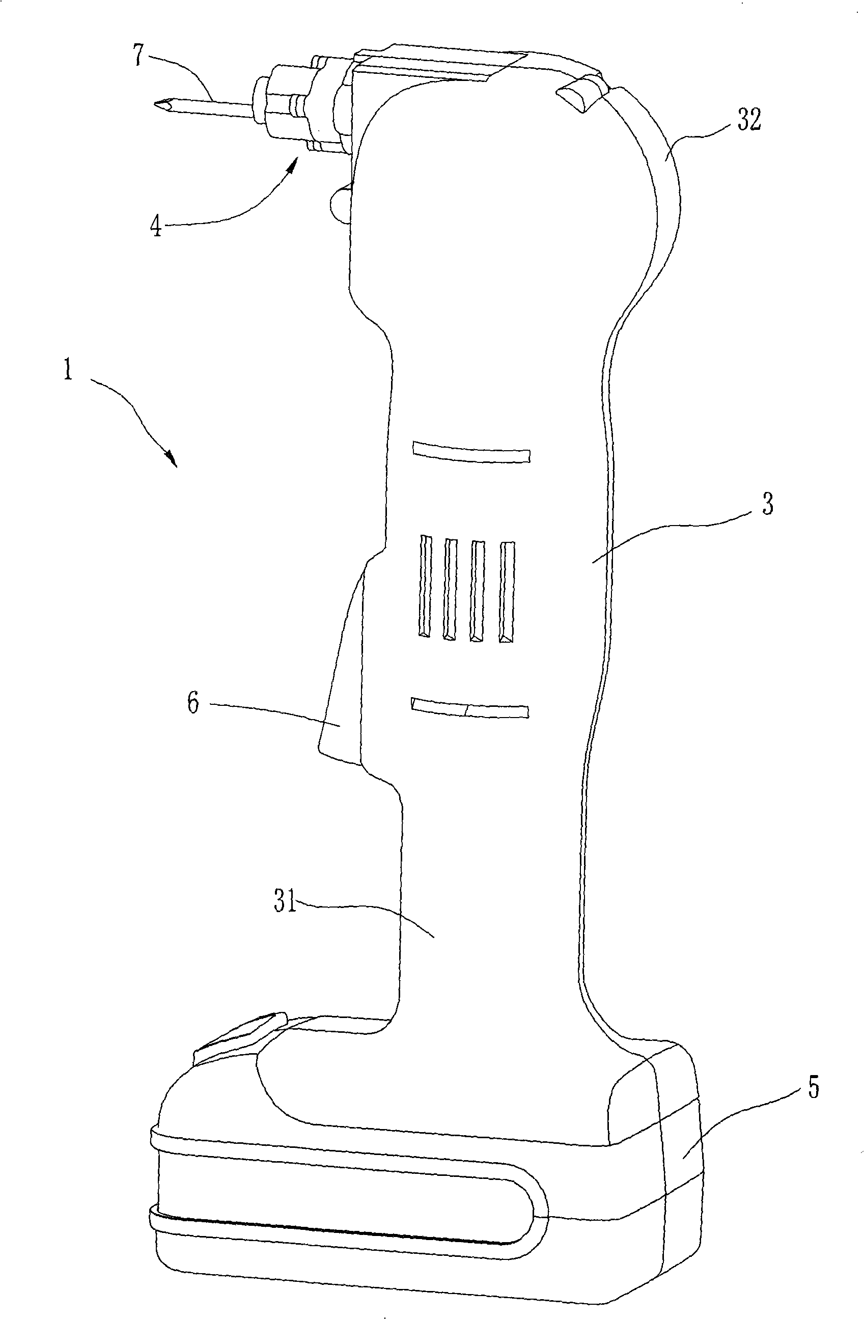
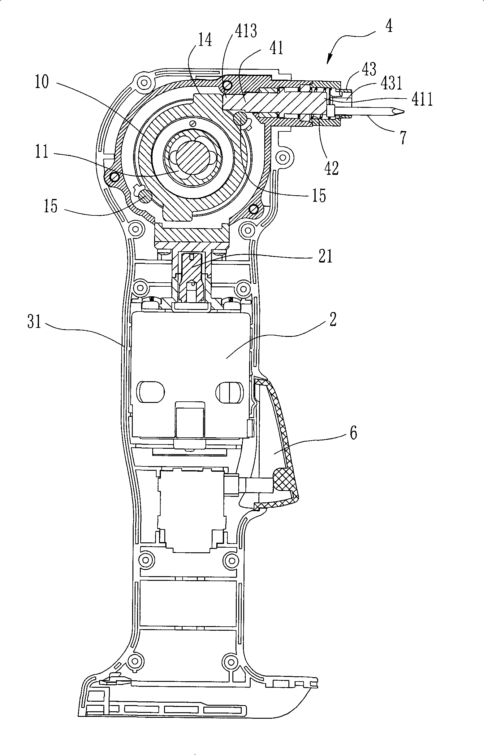
[0025] Such as figure 1 with figure 2 As shown, the nailing gun 1 of this embodiment includes a casing 3 containing the motor 2 and a gun nozzle part 4. The casing 3 is formed by combining two halves of the casing 31, 32 to form an accommodating space. The main part of the casing 3 forms an elongated handle, the upper part of the main part has a hole, and at least a part of the muzzle part 4 protrudes from the hole.

[0026] In this embodiment, the nailer 1 includes a battery pack 5 for powering the motor 2 . However, the power supply mode of the nailing gun disclosed in the present invention is not limited thereto, and AC power can also be used for power supply. The switch 6 is installed on the casing 3 and is connected with the motor control circuit for controlling the start and stop of the motor 2 . The gun nozzle part 4 comprises a nailing rod 41 that can push away the nail 7, and the nail driving rod 41 is substantially perpendicular to the longitudinal direction of t...

Embodiment approach 2

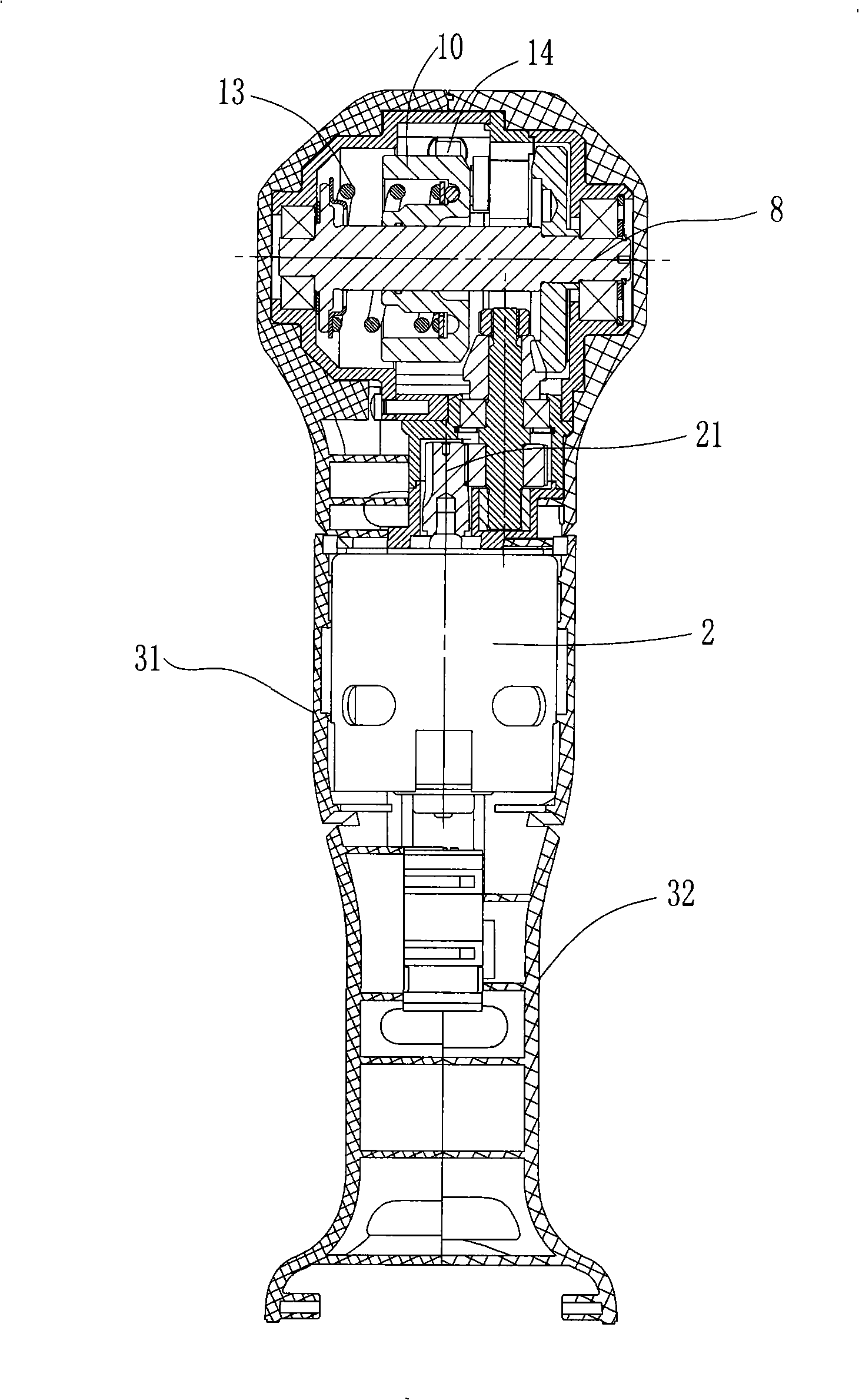
[0036] The nailing gun of present embodiment two is as Figure 8 , Figure 9 with Figure 10 As shown, although the appearance is obviously different from that of Embodiment 1, the casing 30 after removing the battery pack is T-shaped, and the motor 20 is not vertically placed on the handle, but horizontally placed on the gun mouth portion at the front end of the casing 30 40, but its internal transmission mechanism and striking working principle are basically the same, so I won’t repeat them here.

[0037] Except that there are differences in the shapes of individual parts, the significant difference between the second embodiment and the first embodiment in the transmission mechanism and striking principle is that there is no stop pin in the nailing gun of the present embodiment. In actual operation, during the process of driving the nail into a relatively hard object, or the nail has been completely driven into the object, the driving rod may be subjected to a large impact...


PUM


Abstract

The invention relates to a nailing gun, which comprises a machine shell for receiving a motor, and a nailing device, wherein the machine shell also comprises a transmission mechanism for converting rotary movements of the motor into periodical impacting actions to the nailing device, and the transmission mechanism further comprises an impacting assembly for applying the periodical impacting actions to the nailing device. Because the nailing gun adopting the structure of the invention is reasonably provided with the motor and a driving mechanism, the nailing gun has an impact structure, can realize continuous high efficient beats on a nail, and effectively avoids the trouble that a one-off shooting type nailing gun cannot drive in nails under certain working condition.

Description

technical field [0001] The invention relates to a nailing gun, in particular to an electric nailing gun. Background technique [0002] A staple gun is a commonly used hand-held tool with a wide variety. According to the power source, nail guns can be divided into two categories: pneumatic and electric. Among them, the pneumatic nailing gun must have a compressed air source in addition, so its use is limited. The basic structure of the electric nail gun can be summarized as follows: the motor placed in the gun body is connected with the nail rod placed at the gun head through the rotation-linear motion transmission mechanism, so that the electric energy can be converted into reciprocating motion under the control of the switch of mechanical energy. [0003] US Patent No. US6431430 and PCT International Patent Application Publication No. WO2006 / 008546 both disclose an electric nail gun with a crank slider mechanism as a rotation-linear motion transmission mechanism and a ba...

Claims


Application Information

Patent Timeline
Patent Type & Authority Applications(China)
IPC IPC(8): B25C1/06
Inventor 吹拔正敏魏淦陈治国吉利奥姆·凯勒
Owner NANJING CHERVON IND
Why Eureka
Try Eureka