Electric power steering device and method of assembling the same

A technology of electric power steering and steering shaft, which is applied to electric steering mechanisms, electromechanical devices, electric components, etc., and can solve problems such as mixing electrical noise, residual stress, and increased electrical loss

Inactive Publication Date: 2009-04-15
NSK LTD
View PDF5 Cites 27 Cited by
  • Summary
  • Abstract
  • Description
  • Claims
  • Application Information

AI Technical Summary

Problems solved by technology

[0005] However, in the conventional examples described in the above-mentioned Patent Documents 1 to 4, there is such a structure that in a so-called rack-type electric power steering device in which a motor is accommodated in a part of a rack case or a steering gear case, the motor-side connection terminal It is electrically connected to the board-side connection terminals provided on the control board, and directly assembled without intervening an electrical connection wire between the motor and the control board. Thus, the wiring length between the motor and the control board can be reduced to The shortest, can prevent electrical noise from mixing, and can reduce wiring resistance and reduce electrical loss. However, the torque detection value of the torque sensor that detects the torque transmitted to the steering shaft must be input to the control board that controls the motor. In general, the torque sensor is usually installed on the side of the steering wheel away from the rack box or steering gear box, and a long connection cable must be installed between the torque sensor and the control board, so there is an unsolved problem: Electrical noise is mixed in the connecting cable, and electrical loss increases due to the increase in resistance
[0006] Also, in the conventional example described in Patent Document 1, since the electric motor has a direct motor structure, it is not necessary to perform phase matching for connecting the electric motor to the speed reduction mechanism. In the electric power steering device of the shape, since the electric motor and the reduction mechanism need to be fitted with splines or triangular splines, when the electric motor is connected to the reduction mechanism, it is necessary to perform phase matching while rotating the elec

Method used


Image

  • Electric power steering device and method of assembling the same
  • Electric power steering device and method of assembling the same
  • Electric power steering device and method of assembling the same

Examples


Embodiment Construction

[0173] Embodiments of the present invention will be described below with reference to the drawings.

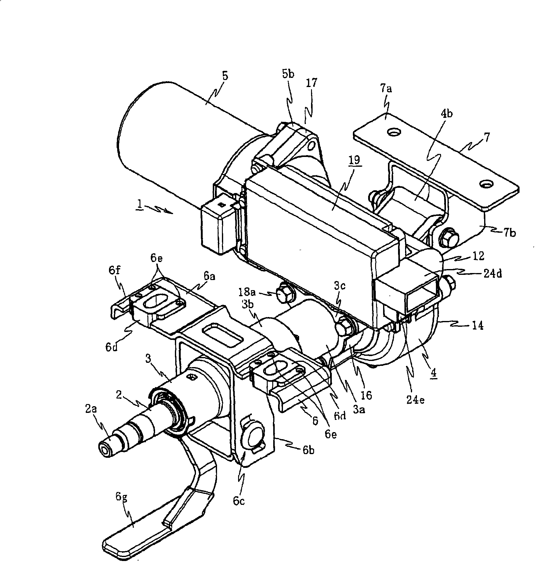
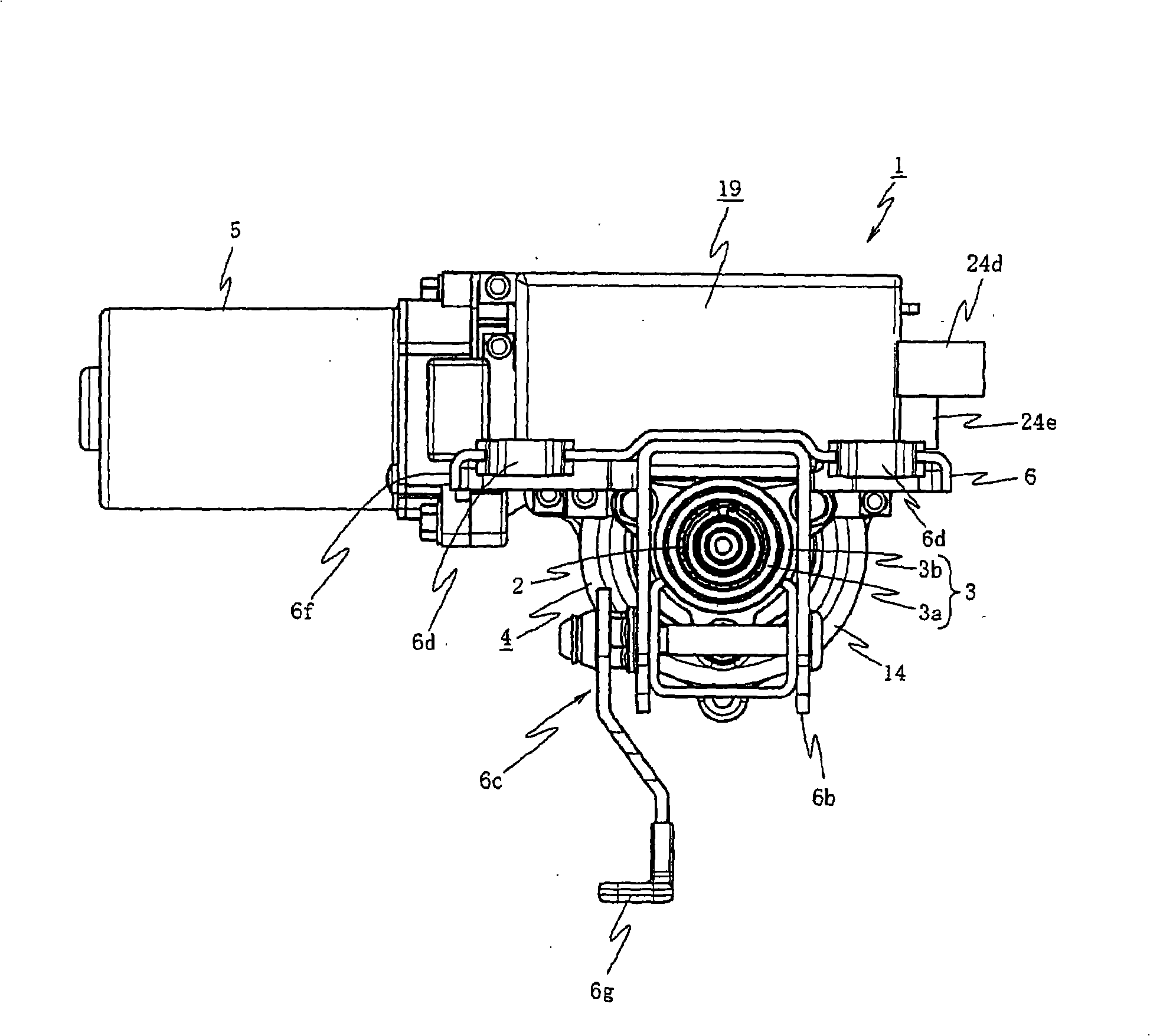
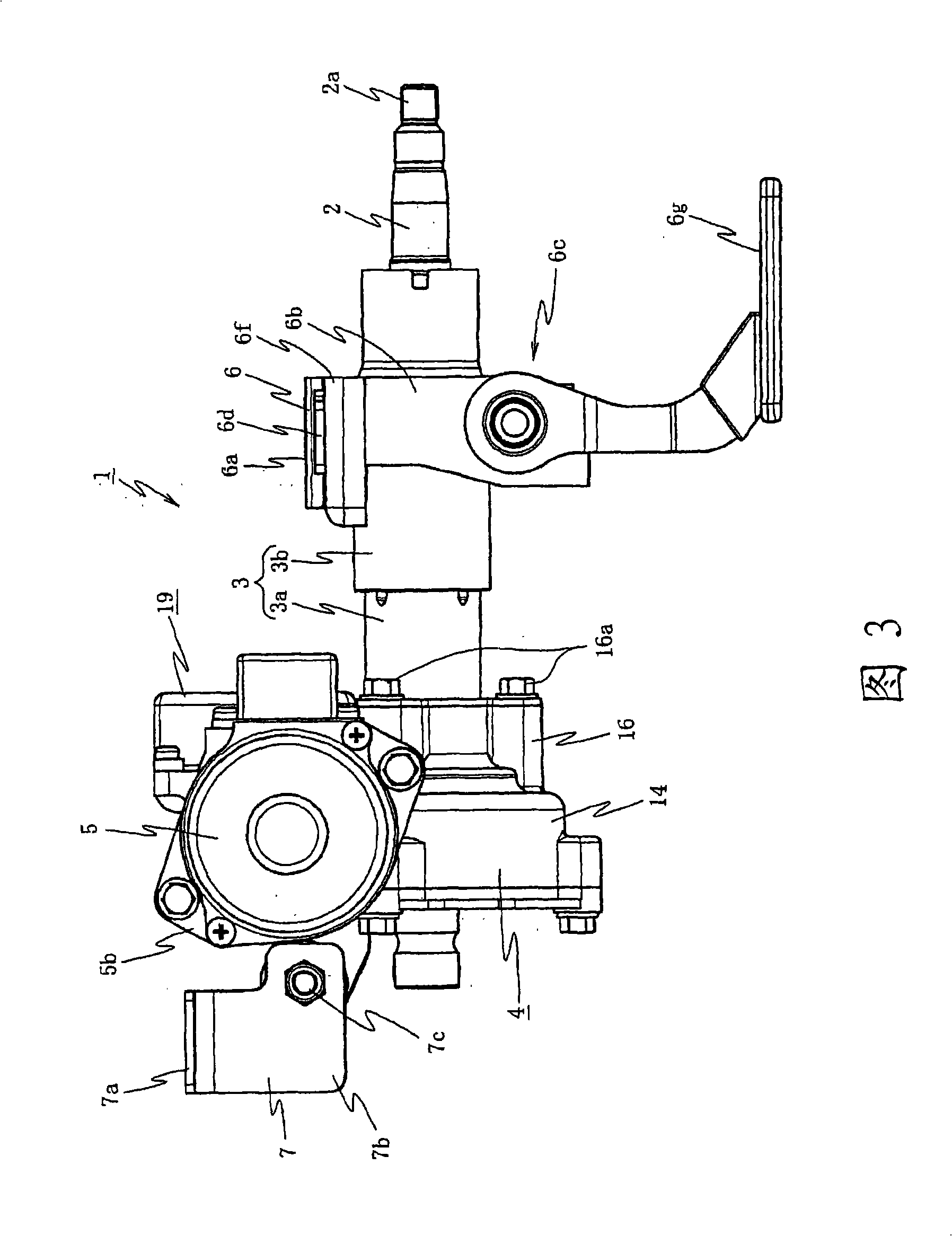
[0174] figure 1 It is a perspective view showing an example of applying the first embodiment of the present invention to a right-hand steering vehicle, figure 2 is the front view, Figure 3 is the left side view, Figure 4 is a top view, Figure 5 and Figure 6 It is an exploded perspective view of the main part.

[0175] exist figure 1 Among them, 1 is a column-type electric power steering device. The steering shaft 2 has a steering wheel mounting portion 2a for mounting a steering wheel (not shown). The steering shaft 2 is rotatably built into a steering column 3. A reduction gear box 4 is connected, and an electric motor 5 constituted by a brush motor is disposed on the reduction gear box 4 . The axial direction of the electric motor 5 extends in a direction perpendicular to the axial direction of the steering column 3 .

[0176] Here, the steering column 3 has a doub...


PUM


Abstract

To provide an electric power steering apparatus in which it is possible to minimize a connection distance between a control unit and an electric motor and surely prevent electric noise from mixing between the control unit and the electric motor as well as to minimize electric resistance and minimize an electric loss by directly connecting the control unit and connection terminals of the electric motor and a torque sensor. A motor control apparatus includes a steering column 3 having inserted therein a steering shaft 2 to which steering torque is transmitted, a reduction gear box 4 coupled to the steering shaft 2, and an electric motor 5 that transmits a steering assisting force to the steering shaft 2 via a reduction mechanism in the reduction gear box 4. The electric motor 5 and a control unit 19 including a control board mounted with a control circuit that controls to drive the electric motor 5 are provided side by side in the reduction gear box 4 and a connection terminal of the electric motor 5 is electrically connected to the control unit 19 directly.

Description

technical field [0001] The present invention relates to an electric power steering device and a method for assembling the same. The mechanism transmits steering power to the steering column. Background technique [0002] As a conventional electric power steering apparatus, for example, there has been proposed an electric power steering apparatus in which a motor is housed in a rack case or a part of a steering gear case that accommodates or mounts a rack shaft in a slidable manner, and the motor is housed to drive the motor. The housing of the control board of the control is formed on the rack case or the steering gear case, when the control board inserted from the opening abuts against a mounting boss formed on the bottom of the housing opposite to the opening The substrate connection terminals provided on the control substrate are electrically connected to the motor-side connection terminals protruding from the motor and provided in the housing (for example, refer to Japa...

Claims


Application Information

Patent Timeline
IPC IPC(8): B62D5/04F16H1/16B62D1/19H02K7/116
Inventor 关根孝明大岛淳儿玉徹也小林诚一清水康博兵头直树远藤茂堀越敦樫本圭司近江保川田秀明篠原茂雄仙波刚下田光夫
Owner NSK LTD
Why Eureka
Try Eureka