
Constant pressure variable radial piston pump

A constant pressure variable, radial column technology, applied in the direction of variable capacity pump components, pumps, multi-cylinder pumps, etc., can solve the problems of affecting the normal operation of the pump, insufficient locking force, falling off of the connecting rod, etc., to achieve simple structure, The effect of high rated pressure and stable operation

Inactive Publication Date: 2009-04-22
董桂敏
View PDF0 Cites 6 Cited by
  • Summary
  • Abstract
  • Description
  • Claims
  • Application Information

AI Technical Summary

Problems solved by technology

[0002] As we all know, with the rapid development of modern industrial technology, the requirements for the hydraulic industry are getting higher and higher. As the power element of hydraulic transmission - the plunger pump, its development trend is high speed, high pressure, large capacity, low noise, and long service life. Changhe mechanical and electrical integration, at present, the return ring on the radial piston pump used abroad is mostly made of composite materials, the price is high, it does not meet the national conditions and it is difficult to find in China; the annular groove inside the plunger is narrow, and the retaining ring is small, so If the locking force is not enough, the circlip cannot catch the connecting rod, causing the connecting rod to fall off from the plunger hole, seriously affecting the normal operation of the pump

Method used


Image

  • Constant pressure variable radial piston pump
  • Constant pressure variable radial piston pump
  • Constant pressure variable radial piston pump

Examples


Embodiment Construction

[0025] In order to further understand the characteristics and effects of the present invention, the following embodiments are given as examples, and detailed descriptions are as follows in conjunction with the accompanying drawings, please refer to Fig. 1— Figure 7 .

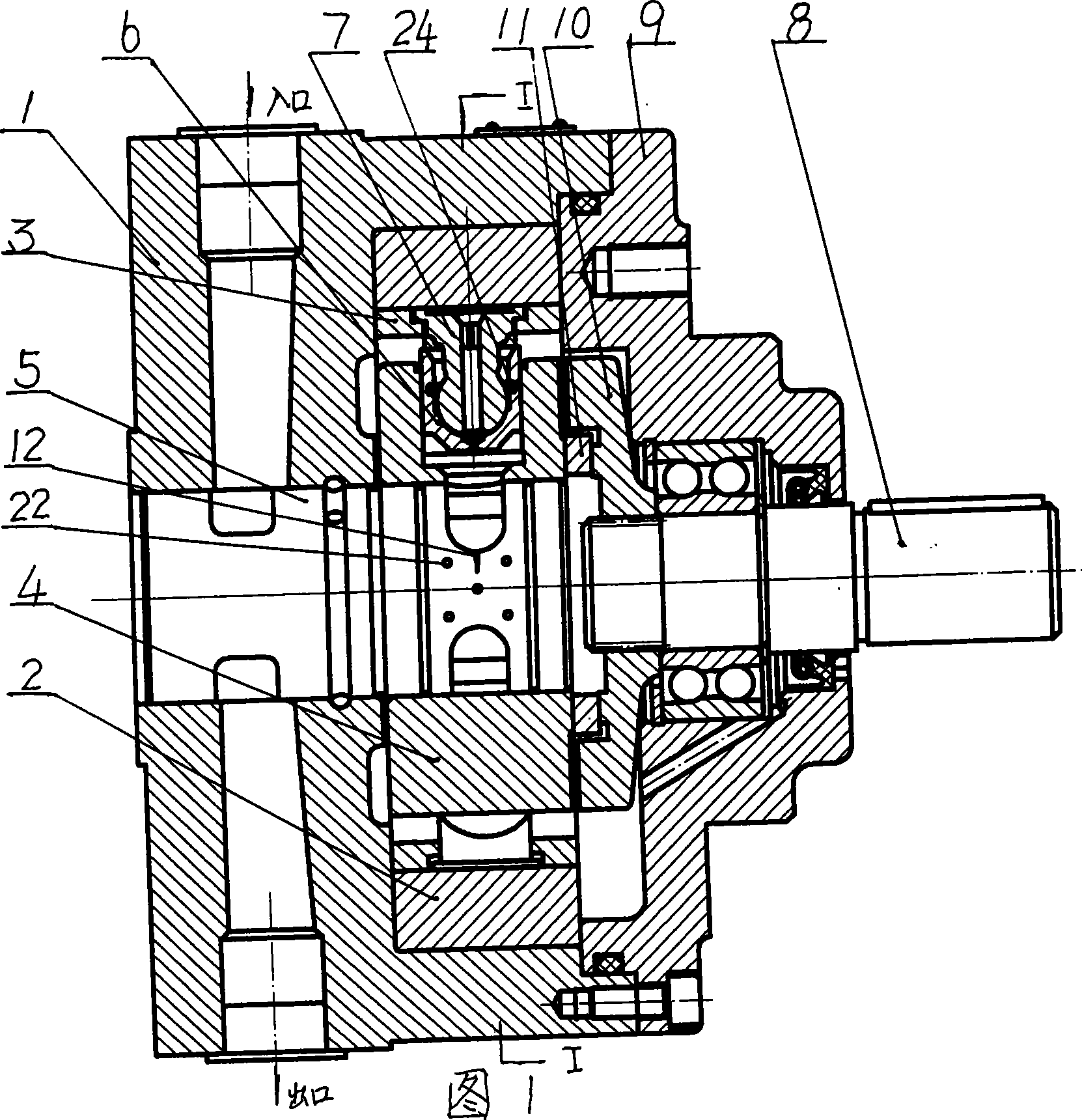
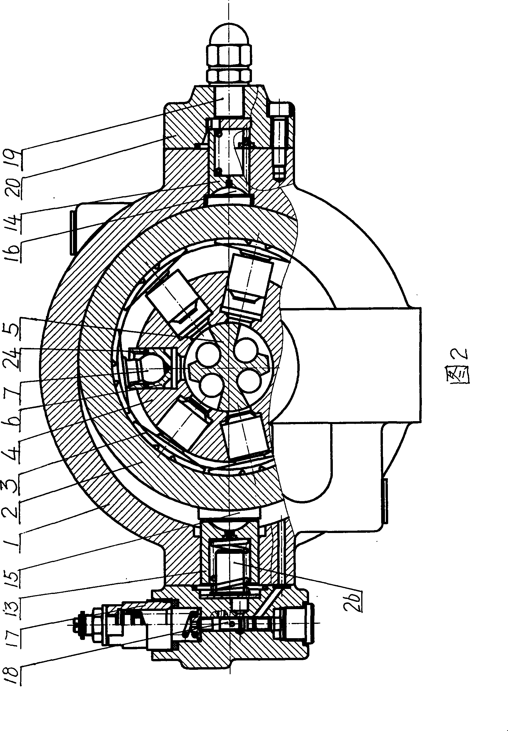
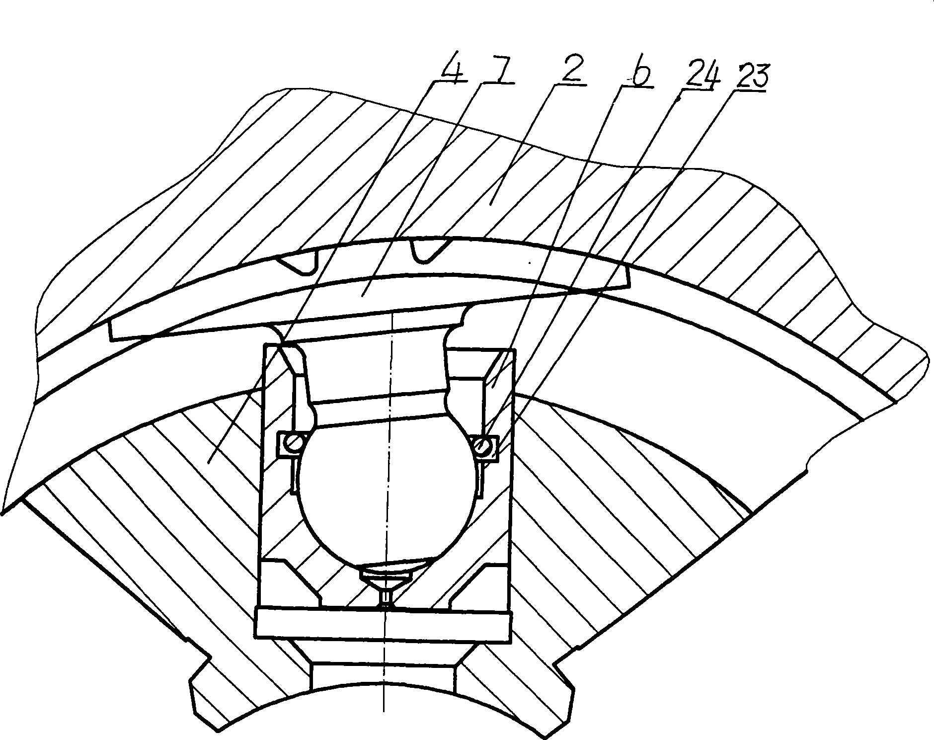
[0026] Figure 1- image 3 As shown: the present invention is mainly composed of a pump casing 1, a stator 2, a return ring 3, a rotor 4, a flow distribution shaft 5, a plunger 6, a connecting rod 7, a transmission shaft 8, a pump cover 12, a coupling 13, and a cross slider 14 , large control plunger 16, small control plunger 17, A slider 18 and B slider 19, manual constant pressure variable valve 20, the inner hole of the pump casing 1 is oblong; the annular stator 2 is slippery with the pump casing 1 , both sides of the inner circle of the stator 2 are respectively matched with the return ring 3, the return ring 3 is made of ZQA19-4 aluminum bronze, the main chemical composition is: Cu=87.34%, Zn=0.05%, Pb=0.077...


PUM


Abstract

The invention relates to a constant-pressure variable radial plunger pump. The inner bore of a pump case is a long circle; an annular stator is in sliding fit with the pump case, two sides of the inner circle of the stator are in movable fit with a return stroke ring respectively, and the return stroke ring adopts ZQA19-4 albronze; a rotor is freely sleeved on a pintle valve, plungers are evenly distributed in the radial direction of the rotor, inner bores of the plungers are provided with wide annular grooves with the width of 2.2 mm, and clamp springs with the diameter of 2.1 mm are arranged in the grooves, so as to increase locking force to a connecting rod ball; a cambered disc surface of a connecting rod is additionally provided with an annular groove B for storing oil, and oil film is generated when the annular groove B rotates at a high speed, so as to improve the lubricating performance and have good wearing resistance; the pintle valve is provided with a sealed annular groove A in the axial direction and provided with five oil storage holes respectively on the side of a V-shaped groove, and oil film is generated when the annular groove A rotates, so as to improve the lubricating performance. The constant-pressure variable radial plunger pump has the advantages of simple structure, small volume, low noise, large locking force of the clamp springs, no disengagement of the plungers and the connecting rod, and high lubricating performance and wearing resistance of parts; and the return stroke ring adopts the ZQA19-4 albronze and has strong wearing resistance, so the whole service life is long.

Description

technical field [0001] The invention relates to a plunger pump, in particular to a constant pressure variable radial plunger pump with high speed, low noise, long service life and simple structure. Background technique [0002] As we all know, with the rapid development of modern industrial technology, the requirements for the hydraulic industry are getting higher and higher. As the power element of hydraulic transmission - the plunger pump, its development trend is high speed, high pressure, large capacity, low noise, and long service life. Changhe mechanical and electrical integration, at present, the return ring on the radial plunger pump used abroad is mostly made of composite materials, the price is high, and it does not meet the national conditions and it is difficult to find in China; If the locking force is insufficient, the circlip cannot catch the connecting rod, causing the connecting rod to fall off from the plunger hole, seriously affecting the normal operation ...

Claims


Application Information

Patent Timeline
Patent Type & Authority Applications(China)
IPC IPC(8): F04B1/04F04B53/14
Inventor 董桂敏
Owner 董桂敏
Learn More