Mechanical and hydraulic combined transmission device

A compound transmission and hydraulic technology, which is applied in the transmission device, fluid transmission device, control device, etc., can solve the problems of driver's operation error, complex structure, low transmission efficiency, etc., and achieve enhanced traffic capacity, high transmission efficiency, and increased speed Effect

Inactive Publication Date: 2009-04-22
赵宏坚 +1
View PDF0 Cites 22 Cited by
  • Summary
  • Abstract
  • Description
  • Claims
  • Application Information

AI Technical Summary

Problems solved by technology

The shortcomings of this hydraulic-mechanical compound transmission scheme are: (1) the first stage is hydraulic transmission, and its transmission efficiency is low; (2) there is circulating power in the power flow direction of the second stage; (3) the hydraulic power in the third stage The ratio of power flow and mechanical power flow is constantly changing, and the total transmission efficiency after confluence is unstable; (4) The operation method is complicated and difficult to master, which is not common to the general operation essentials of ordinary cars, and it is easy for the driver to make operation errors and cause safety accidents
"Application of Hydraulic Coupling and Energy-saving Technology" (edited by Liu Yingcheng and Yang Naiqiao, published by Chemical Industry Press, first edition in January 2006) published the selection of transmission mode of speed-regulating hydraulic coupling (Chapter 6, Section 7, Section 3, Table 6-8), among the various speed-regulating transmission methods listed in this table, the transmission efficiency of the single-motor series-connected speed-regulating fluid coupling is low, the power of the hydraulic coupling is large, and multiple motors are connected in series or parallel The structure of the speed-regulating hydraulic coupling mechanism is complex and the investment is large

Method used


Image

  • Mechanical and hydraulic combined transmission device
  • Mechanical and hydraulic combined transmission device
  • Mechanical and hydraulic combined transmission device

Examples


no. 1 example

[0040] This embodiment is that the mechanical and hydraulic compound transmission device of the present invention is applied to the transmission system of large equipment, combined with the attached figure 1 Describe in detail.

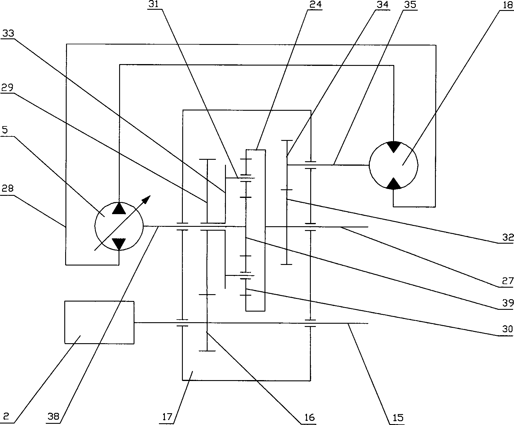
[0041] The engine 2 is connected to the transmission planetary gearbox 17, and the half shaft 27 is connected to the transmission load working machine; the engine 2 is connected to the transmission transfer shaft 15 to rotate, and the transfer shaft 15 is linked and fastened to the transfer shaft 15 installed in the planetary gearbox 17. The moving gear 16 rotates, the transfer gear 16 meshes and drives the transition gear 29 to rotate, and the transition gear 29 is linked and fastened to the connected frame 33 to rotate. Rotate and drive the planetary gears 30 respectively set on each planetary gear shaft 31 to rotate. The planetary gears 30 rotate around the planetary gear shafts 31 and revolve around the axis of the frame 33 at the same time. The p...

no. 2 example

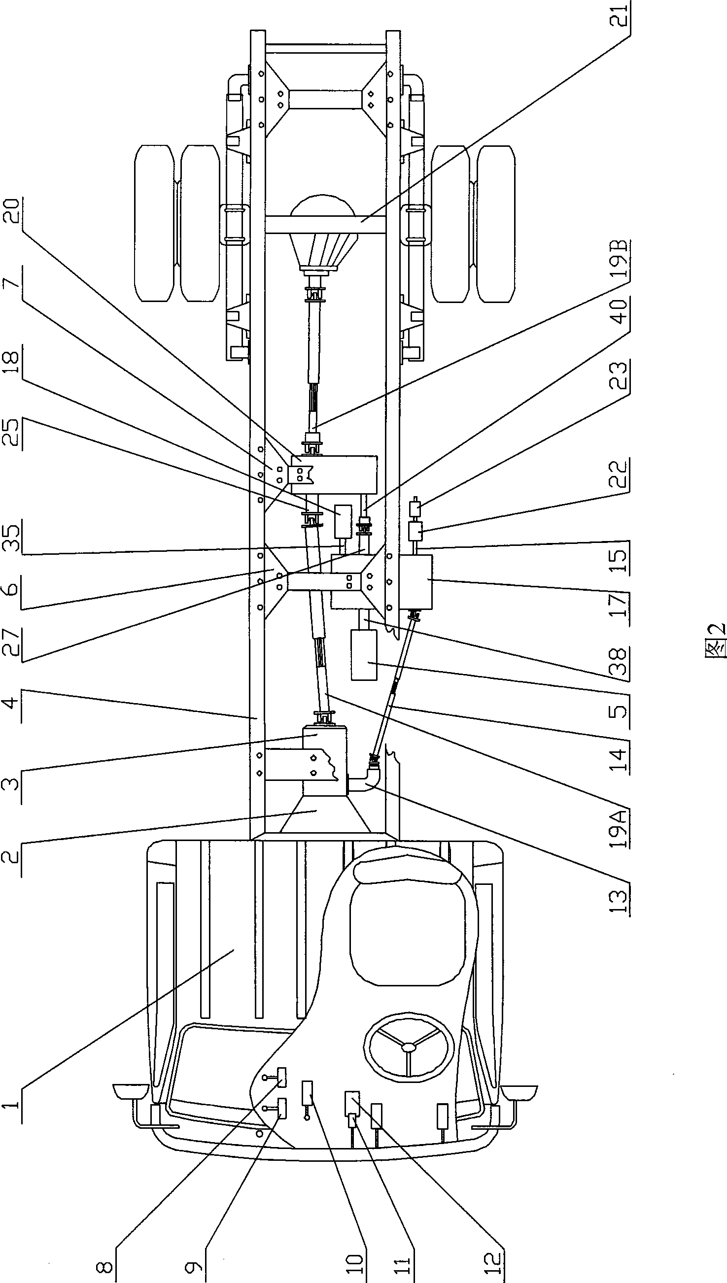
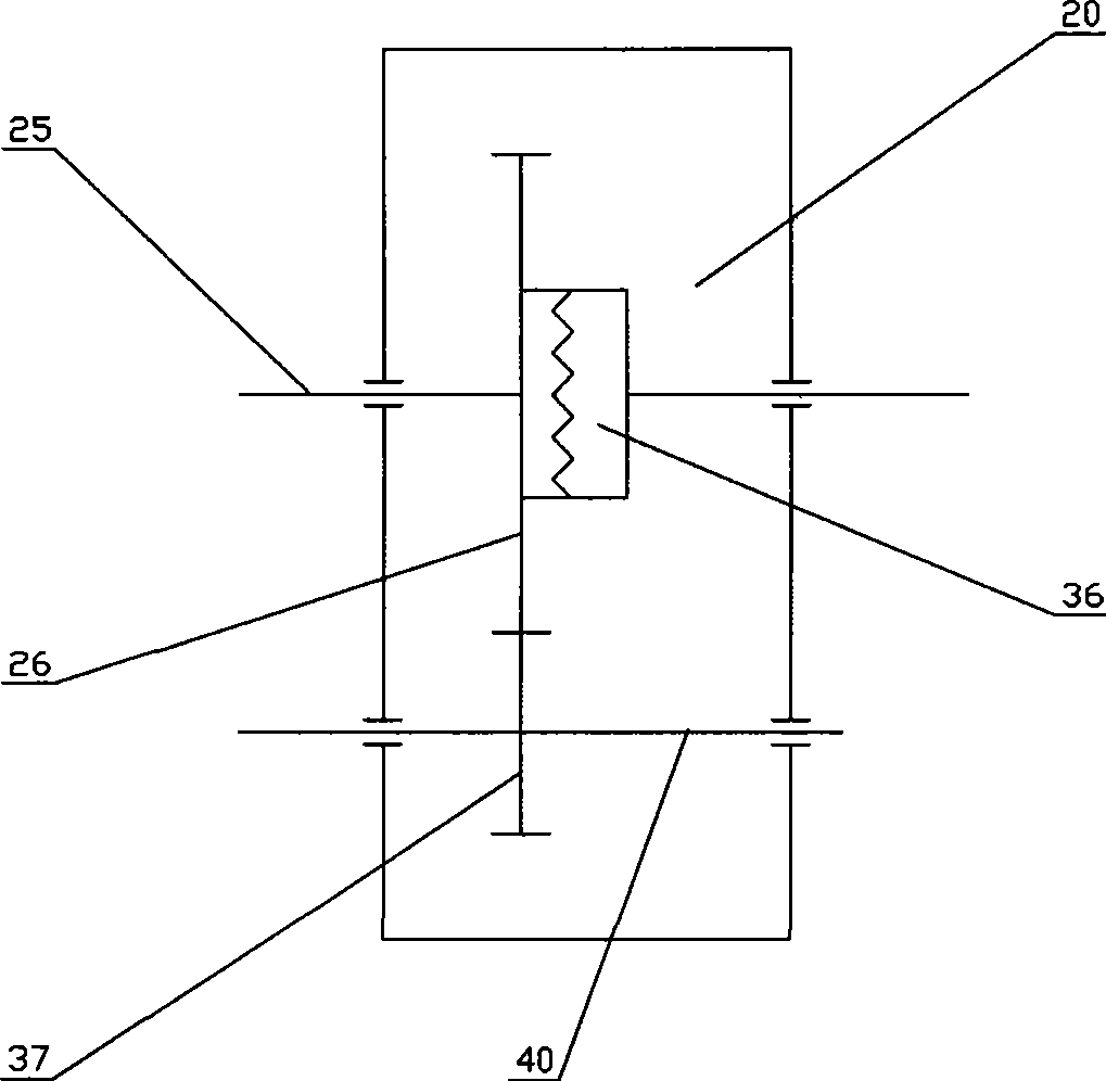
[0048] Fig. 2 is the structural diagram of the second embodiment of the mechanical and hydraulic compound transmission device of the present invention, image 3 It is a structural diagram of the reduction box in the second embodiment, and Fig. 4 is a supplementary transmission schematic diagram of the structure of the second embodiment of the present invention.

[0049] Figure 2 and image 3As shown, the cab 1, the engine 2, the transmission 3, the front support 6, and the rear support 7 are respectively installed on the vehicle frame 4, the planetary gearbox 17 is suspended and installed under the front support 6, and the reduction box 20 is suspended and installed on the rear support. 7 times. The engine 2 is connected to the transmission 3, and the power take-off 13 is installed on the power take-off interface of the transmission 3. The power take-off 13 has a clutch device connected with the transmission 3 for transmission and separation. The device 13 is connected to th...

no. 3 example

[0056] FIG. 5 is a structural diagram of a third embodiment of the present invention, which will be described in detail below in conjunction with FIG. 5 .

[0057]The engine 2, the transmission 3, and the front bracket 6 are installed on the vehicle frame 4, and the planetary gearbox 17 is suspended and installed under the front bracket 6; the engine 2 is connected to the transmission front transmission shaft 19A through the transmission 3, and the front transmission shaft 19A is connected to the transmission planetary gearbox The transfer shaft 15 of 17, the transfer gear 16 is fixed on the transfer shaft 15, and the transfer gear 16 meshes with the transmission transition gear 29; the transition gear 29 and the tie frame 33 are fixedly connected with the same axis, and the output end of the tie frame 33 is vertically uniform Two or three planetary gear shafts 31 are installed, and a planetary gear 30 is set on each planetary gear shaft 31, and the planetary gear 30 meshes wit...


PUM


Abstract

The invention relates to a mechanical and hydraulic compound transmission device which comprises an engine, a speed changer, a planetary gear box, a hydraulic variable pump, a hydraulic motor and a reduction gearbox; the engine is sequentially connected with the transmission speed changer and the planetary gear box, and a planetary gear mechanism of the planetary gear box distributes the power driven by the motor to respectively drive the hydraulic variable pump and a center gear; the hydraulic variable pump is sequentially connected with a transmission hydraulic motor and a half shaft, the half shaft converges mechanical power flow driven by the center gear and hydraulic power flow driven by the hydraulic motor and protrudes outside the planetary gear box to output the power, and a transmission gear box is connected with the half shaft to redrive a rear shaft to drive a vehicle. A special vehicle refit by the technology with a single-engine configuration can run at a stepless variable speed in a mechanical and hydraulic compound transmission mode, meanwhile, the vehicle can drive a vehicle-mounted operating device in the mechanical transmission mode; during transition, the mechanical transmission mode can be adopted to cause the device to run quickly, the power system occupies little vehicle space, and has low emission, high transmission efficiency and low oil consumption.

Description

technical field [0001] The invention relates to a transmission device, in particular to a mechanical and hydraulic compound transmission device. Background technique [0002] Many engineering operations need to use the chassis of the car to carry the operating equipment while driving and perform various construction operations, such as road sweepers and harvesters. The power transmission of some of the operating devices is realized by an engine through a mechanical transfer case to simultaneously drive the vehicle and the operating device to work, such as the transmission device of the harvester. However, because road sweepers and the like need to constantly change the driving speed during driving, and the engine speed is changed when the speed is changed, the work quality will be reduced, so the road sweepers and other operating devices cannot use this power transmission method. [0003] At present, there are two solutions for the power transmission of a road sweeper opera...

Claims


Application Information

Patent Timeline
Patent Type & Authority Applications(China)
IPC IPC(8): F16H47/04B60K17/04B60K20/00
CPCF16H47/04
Inventor 赵宏志赵宏坚
Owner 赵宏坚
Why Eureka
Try Eureka