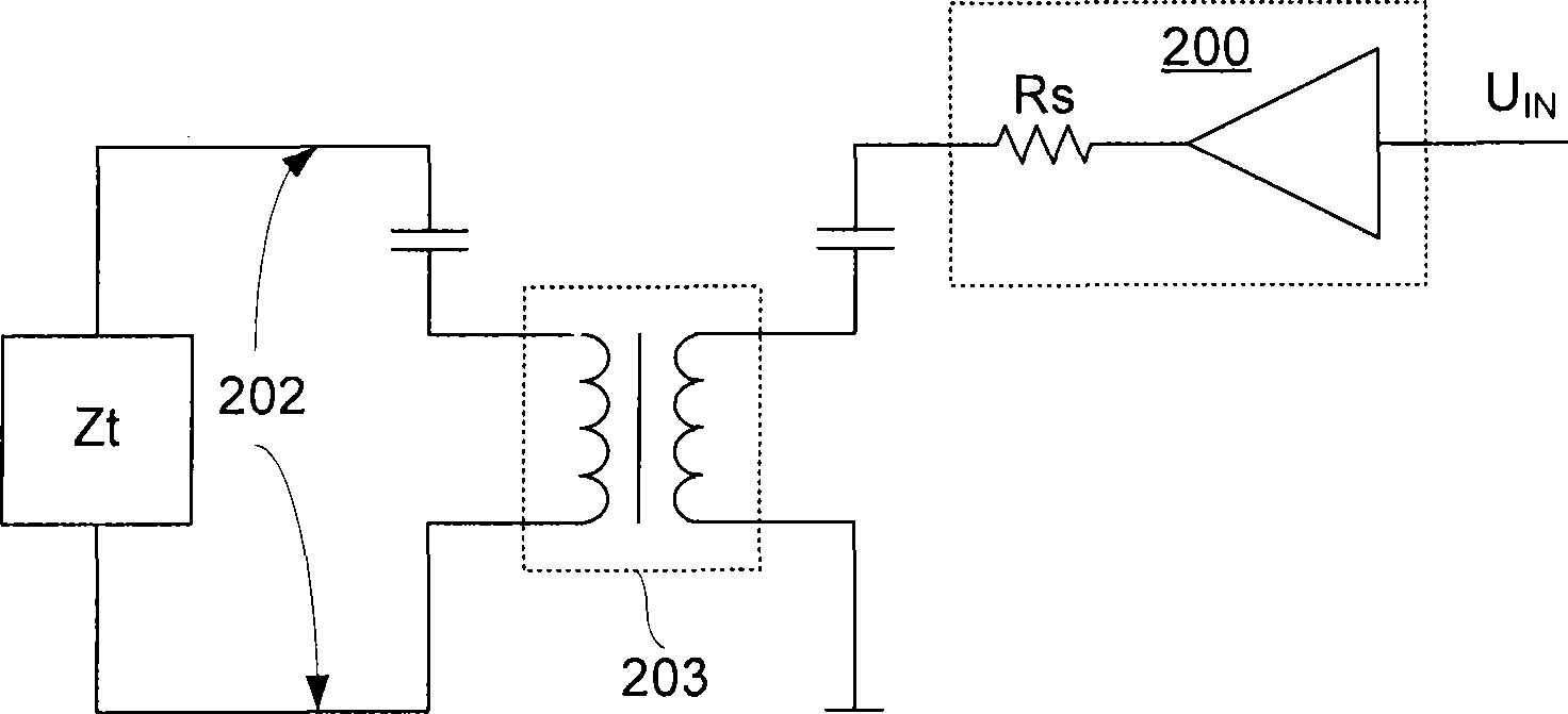
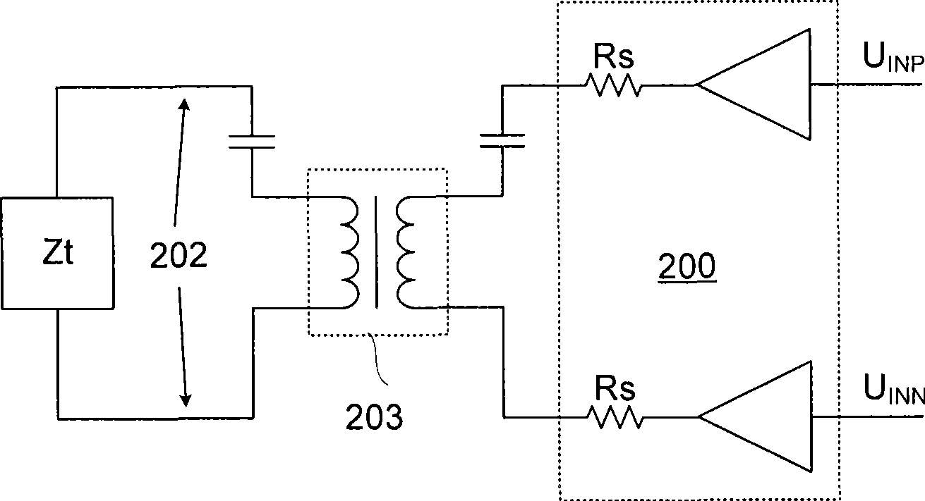
Output coupling and filter circuit for power line carrier communication

A technology of power line carrier and output coupling, which is applied in distribution line transmission system, multi-terminal pair network, frequency selective two-terminal pair network, etc. It can solve the problems of destroying high-impedance state and difficult design of output filter

Inactive Publication Date: 2009-04-22
MIARTECH
View PDF0 Cites 24 Cited by
  • Summary
  • Abstract
  • Description
  • Claims
  • Application Information

AI Technical Summary

Problems solved by technology

However, the addition of a band-pass filter will destroy the high-impedance state that should be in the receiving state,

Method used


Image

  • Output coupling and filter circuit for power line carrier communication
  • Output coupling and filter circuit for power line carrier communication
  • Output coupling and filter circuit for power line carrier communication

Examples


Embodiment Construction

[0036] The purpose of the present invention is to add a band-pass filter after the power amplifier of the power line carrier modem, so that the carrier signal sent to the power line has higher spectral purity, and still keep the circuit in a high-impedance state in the receiving state. The following first describes the structure of the band-pass filter with a practical example.

[0037] see figure 2As shown, an embodiment of the present invention adopts a 4th-order bandpass filter, and its basic equivalent circuit includes two capacitors C1, C2 and two inductors L1, L2, wherein capacitor C1 and inductor L1, capacitor C2 and inductor L2 are respectively A series resonant circuit 303 and a parallel resonant circuit 304 are formed, and the two LC circuits 303 and 304 are respectively tuned to the center frequency of the carrier signal. In addition, the power amplifier 300 can be regarded as a signal source 301 with an output internal resistance Rs. RL is the equivalent load. ...


PUM


Abstract

The invention discloses an output coupling and filter circuit for power line carrier communication, and the circuit is used for coupling the output signals of a power amplifier in the carrier communication system to the power distribution line. A first serial resonant tank is connected with a power amplifier. The first serial resonant tank is harmonic with the center frequency of the carrier signals. An isolation transformator is provided with a first winding, a second winding and a third winding. The first winding is connected with the first serial resonant tank. The second winding is connected with the power distribution line. A shunt-resonant circuit and a switching element are connected with the two terminals of the third winding in parallel after the shunt-resonant circuit and the switching element are connected in series. The switching element is turned on or off under the control of a control signal so as to control the disconnection or connection of the shunt-resonant circuit and the third winding.

Description

technical field [0001] The invention relates to a signal processing process from a carrier power amplifier to a power distribution system in a power line carrier communication system, in particular to an output coupling and filter circuit for power line carrier communication. Background technique [0002] The communication signal can be coupled to the power distribution system using a power line modem to achieve the purpose of using the widely existing power line to transmit data. [0003] However, unlike the wireless communication system, since the main function of the power line is to supply power to various electrical appliances with complex characteristics, its load characteristics on the carrier signal are a very drastic change, which will vary with the signal frequency and time. It varies in a wide range. For the carrier signal conforming to the European standard EN-50065, its frequency should be between 9 and 145KHz. For the carrier signal of this frequency range, the...

Claims


Application Information

Patent Timeline
IPC IPC(8): H04B3/54H03H11/02H03H11/04
Inventor 宋朝盛
Owner MIARTECH
Why Eureka
Try Eureka