Method and apparatus to compensate AM-PM delay mismatch in envelope restoration transmitter

A technology of transmitters and transceivers, applied in the parts, electrical components, transmission systems, etc. of amplifying devices, can solve problems such as transmission time difference sensitivity, and achieve the effect of optimizing performance

Inactive Publication Date: 2009-04-22
NOKIA CORP
View PDF1 Cites 10 Cited by
  • Summary
  • Abstract
  • Description
  • Claims
  • Application Information

AI Technical Summary

Problems solved by technology

[0003] However, it has been recognized that ER-based systems are sensitive to transit time differences between

Method used


Image

  • Method and apparatus to compensate AM-PM delay mismatch in envelope restoration transmitter
  • Method and apparatus to compensate AM-PM delay mismatch in envelope restoration transmitter
  • Method and apparatus to compensate AM-PM delay mismatch in envelope restoration transmitter

Examples


Example Embodiment

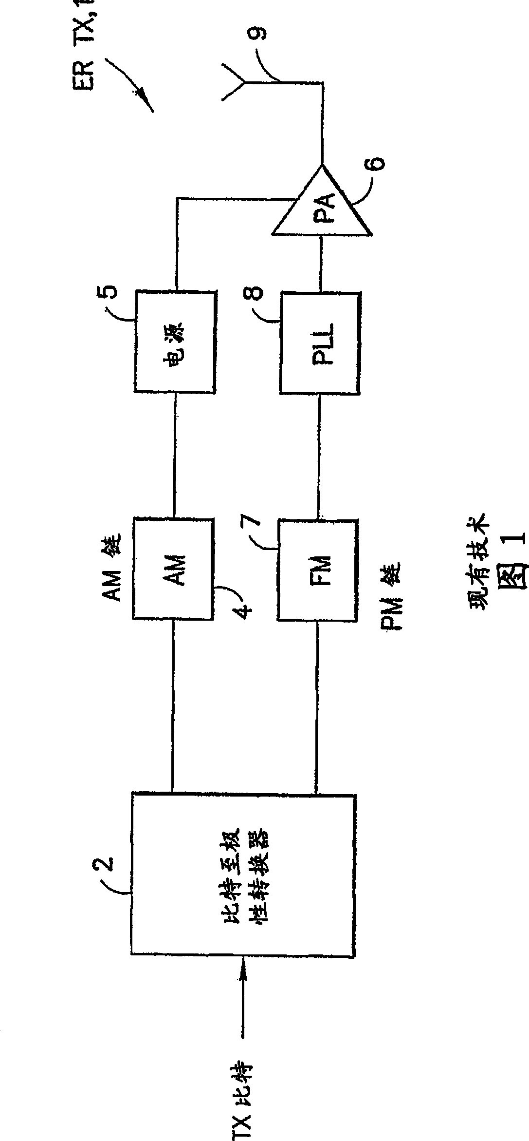
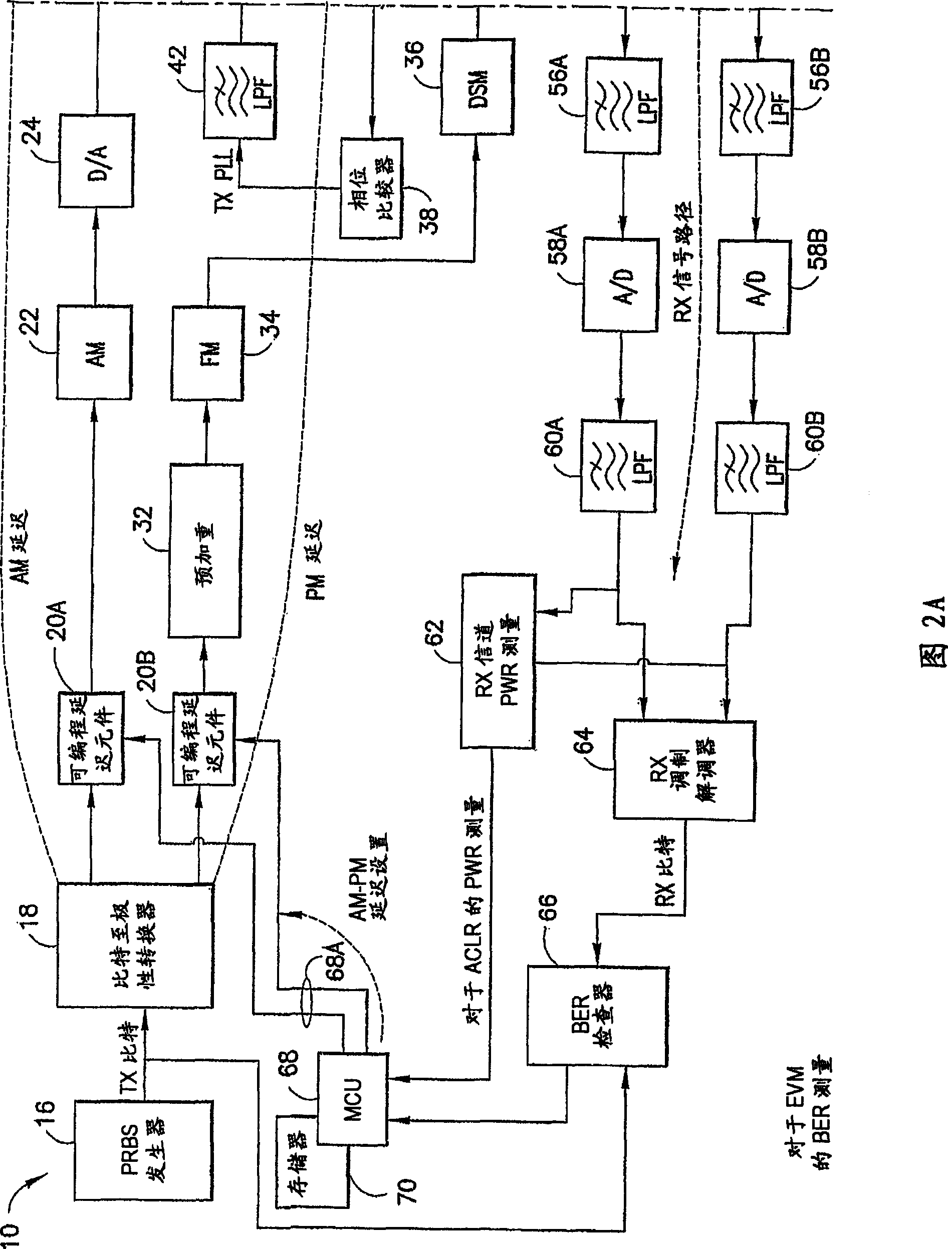
[0026] As mentioned above, the presence of delay mismatch in the AM and PM signal chains of the ER transmitter can reduce ACLR and EVM performance. According to an aspect of the present invention, the effect of the delay mismatch is detected using the receiver after the TX signal loops back to the receiver. In this way, the effect of the delay mismatch is detectable using the existing RX measurement function, avoiding additional circuitry, cost and complexity.
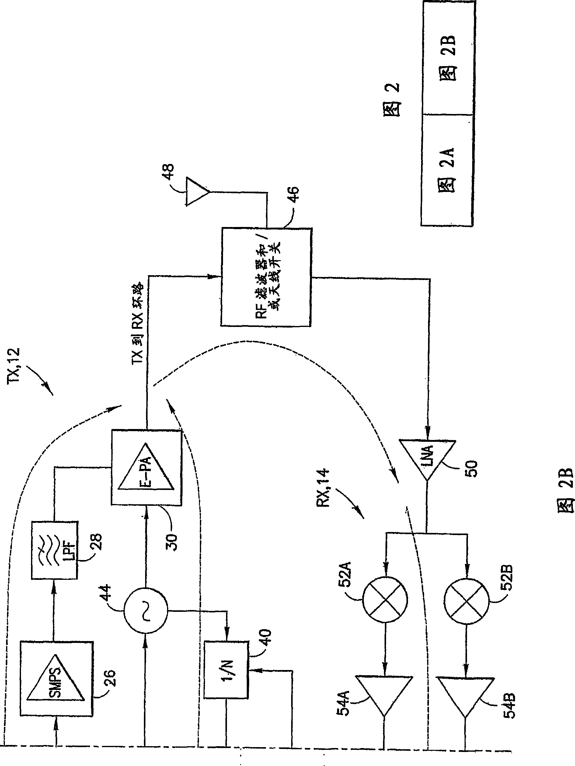
[0027] FIG. 2 is a block diagram of the ER RF transceiver of the mobile station 10 according to the present invention. The receiver (RX) 14 is used to adjust the AM and PM path delays of the transmitter (TX) 12. As used herein, the term "mobile station" can include cellular radio telephones with or without multi-row displays; personal communication system (PCS) terminals that can combine cellular radio telephones with data processing, fax, and data communication capabilities; can include Wireless phones, pagers, Internet / I...


PUM


Abstract

An RF transceiver includes an Envelope Restoration (ER) transmitter (TX) and a receiver (RX). A method includes providing the TX with at least one programmable delay element in at least one of an AM path and a PM path; making an RF connection between an output of the TX and an input of the RX; and responsive to an output of the RX when receiving a signal through the RF connection, determining at least one delay value for use in programming the at least one programmable delay element. Making an RF connection includes measuring an effect of a delay mismatch between the AM path and the PM path for use in determining the at least one delay value. In one embodiment measuring performs a power measurement such as an Adjacent Channel Leakage Ratio (ACLR) power measurement, the delay value is determined as being a value that minimizes the ACLR, and the RX is tuned, when receiving a signal through the RF connection, to an RX carrier frequency that is about one channel spacing away from a TX carrier frequency. In another embodiment measuring performs an Own-Channel Power (OCP) power measurement, the delay value is determined as being a vale that maximizes the OCP, and the RX is tuned to an RX carrier frequency that is substantially equal to a TX carrier frequency. In another embodiment measuring performs a signal quality measurement, such as a Bit Error Ratio (BER) measurement, the delay value is determined as being a value that minimizes the BER, and the RX is tuned to an RX carrier frequency that is substantially equal to a TX carrier frequency.

Description

technical field [0001] The present invention relates generally to wireless radio frequency (RF) transmitters, such as those used in cellular mobile stations, and more particularly to envelope restoration (ER) RF transmitters in which symbols are represented using phase and amplitude components rather than complex In-phase / quadrature-phase (I / Q) components of . Background technique [0002] Figure 1 is a simplified block diagram of the structure of an ER transmitter (TX) 1 comprising an amplitude modulation (AM) chain and a phase modulation (PM) chain. The bits to be transmitted are input to a bits to polar converter 2 which outputs an amplitude signal to an amplitude modulator (AM) 4 . The AM 4 provides (after digital-to-analog conversion) a signal for controlling the output level of a TX power amplifier (PA) 6 by using a controllable power supply 5 . The bit-to-polarity converter 2 also outputs a phase signal to a frequency modulator (FM) 7, which in turn outputs the sign...

Claims


Application Information

Patent Timeline
IPC IPC(8): H04B1/52H04B1/10H04B1/04H03F1/02
CPCH03F2200/294H03F1/0222H03F2200/372H04B1/0475H03F2200/331H03F1/02H04B1/04H04B1/16
Inventor 朱西·韦普萨莱南米卡·阿马莱南
Owner NOKIA CORP
Why Eureka
Try Eureka