Method for making large size column mirror grating

The technology of a lenticular lens grating and a manufacturing method, which is applied in the field of optical device processing, can solve the problems that the large-size lenticular lens grating cannot meet the precision requirements, the surface shape of the bonding part is difficult to control, and the processing equipment requires high requirements, so as to improve the surface accuracy and operate The effect of simplicity and great flexibility

Active Publication Date: 2009-04-29
SUPERD CO LTD
View PDF0 Cites 2 Cited by
  • Summary
  • Abstract
  • Description
  • Claims
  • Application Information

AI Technical Summary

Problems solved by technology

Obviously, since the slices of two lenticular gratings used for splicing cannot be processed to be perfectly symmetrical, the gap at the bonding part will be more obvious, and the surface shape of the bonding part is not easy to control, so that the generated large-size lenticular grating cannot satisfy The precision requirement in use, that is, the quality of the large-size lenticular grating produced by this method depends on the precise cutting and alignment of the spliced ​​lenticular grating, which has high requirements on processing equipment
In addition, since this method is to bond two existing lenticular gratings, in order to ensure that the optical characteristics of the large-scale lenticular grating at the joint surface are consistent with those at the non-joint surface, it is necessary to select a Adhesives with the same refractive index as the lenticular lens grating, obviously, this also has great difficulties in the selection of adhesives

Method used


Image

  • Method for making large size column mirror grating
  • Method for making large size column mirror grating
  • Method for making large size column mirror grating

Examples


Embodiment 1

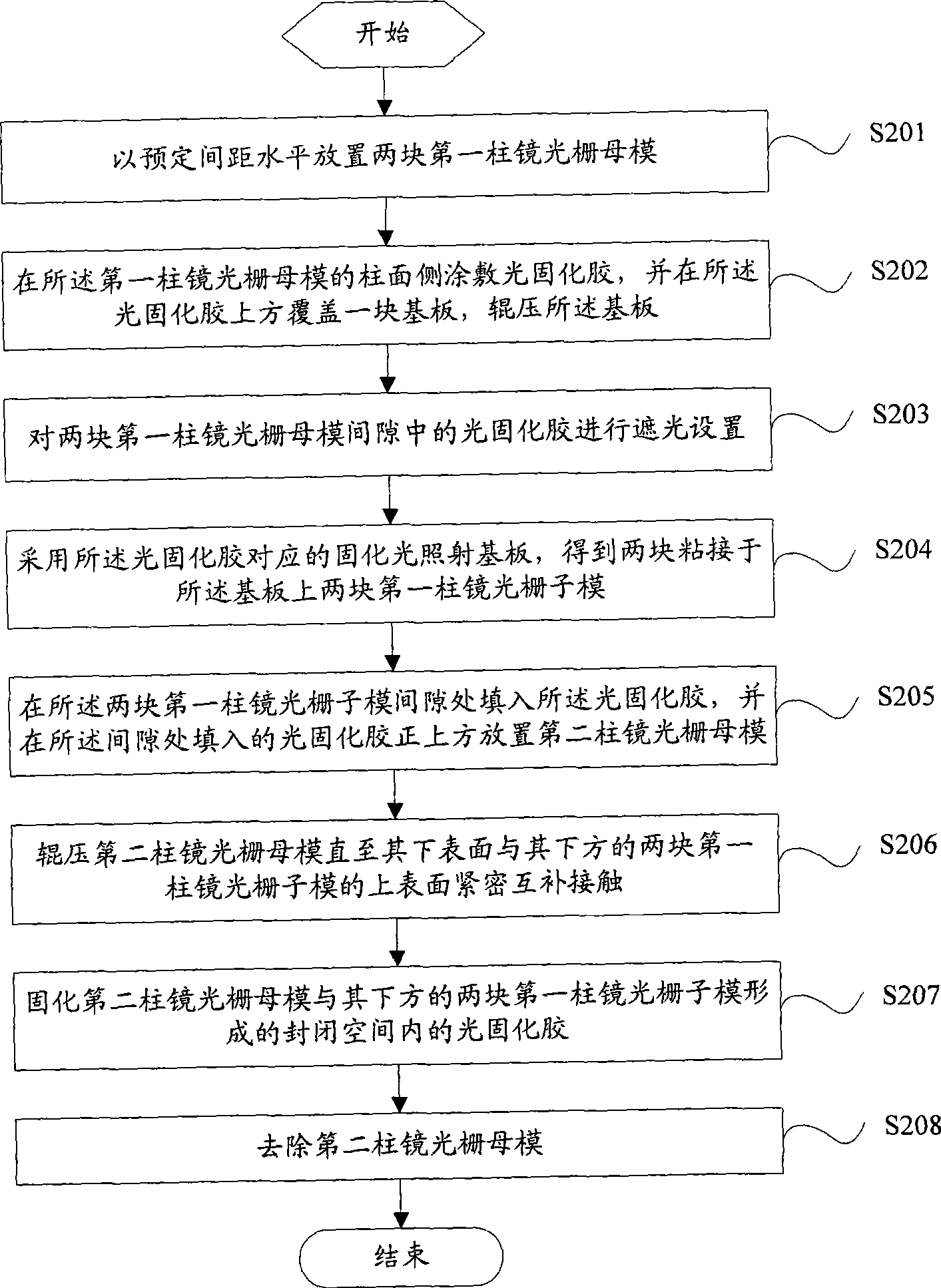
[0049] figure 2 Shown is a production flow chart of a large-size lenticular grating provided in this embodiment, including the following steps:

[0050] S201: Horizontally place two first lenticular master molds at a predetermined distance.

[0051]When setting, the two first lenticular grating master molds are at the same horizontal position, and the cylindrical generatrices of the two first lenticular grating master molds are parallel to each other, and the two first lenticular grating master molds are not in contact with each other . The distance between the complete groove surfaces of any two first lenticular master molds closest to each other is a positive integer multiple of the grating pitch of the first lenticular master mold. Here, the groove surface is: the interface between two adjacent cylindrical lenses on the cylindrical lens grating. Preferably, the predetermined distance between the two first lenticular master molds is determined by the third lenticular mas...

Embodiment 2

[0067] Figure 10 Shown is a production flow chart of a large-size lenticular grating provided in this embodiment, including the following steps:

[0068] S1001: Apply light-curing glue on the cylindrical surface of the fourth lenticular master mold placed horizontally, and cover a second substrate with a size much larger than the fourth lenticular master mold above the light-curing glue, Rolling the second substrate. Wherein, the light-curing glue is consistent with the light-curing glue used in Embodiment 1, and the size of the second substrate is much larger than the size of the fourth lenticular lens grating master mold. The schematic diagram of the specific device is as Figure 11 As shown: the fourth cylindrical lens grating master mold 13 is placed horizontally on the glass substrate 12 , the upper surface of the fourth cylindrical lens grating master mold 13 is coated with a photocurable glue 14 , and the photocurable glue 14 is covered with a second substrate 15 . ...


PUM


Abstract

The invention discloses a method for manufacturing a large-size cylindrical lens grating, which comprises the following steps: step one, at least one first cylindrical lens grating sub mold is generated on a substrate through at least one cylindrical lens grating case mold and light-curing adhesive; and step two, when the number of the first cylindrical lens sub molds generated on the substrate in the step one is one, the same light-curing adhesive is adopted, and a cylindrical lens grating with the same specification as the first cylindrical lens grating case mold is used as a case mold for widening the first cylindrical lens grating sub mold; and when the number of the first cylindrical lens grating sub molds generated on the substrate in the step one is two, the same light-curing adhesive is used to fill the clearance between every two first cylindrical lens gratings, and the first cylindrical lens grating case mold is used as the case mold so as to shape and cure light-curing adhesive at the clearance position between every two first cylindrical lens grating sub molds and make every two first cylindrical lens grating sub molds connected. The method has the advantages of simple operation, wide selective range of refractive index of manufactured cylindrical lens grating, high surface precision of the produced cylindrical lens grating, and good uniformity.

Description

technical field [0001] The invention relates to the field of optical device processing, in particular to a method for manufacturing a large-scale lenticular grating. Background technique [0002] Lenticular gratings are one of the most commonly used gratings in the field of optoelectronics. For example, in the field of stereoscopic displays, lenticular gratings are indispensable. At present, due to various factors in the field of optical device processing and equipment, the size of the master mold for making lenticular lens gratings is limited. The width of the largest lenticular lens gratings available on the market is generally about 1.4 meters. In actual production, Lenticular lens gratings with larger widths are often required. Wherein, the width direction of the lenticular grating is the direction in which the lenticular lenses are arranged. [0003] In the prior art, at least two existing lenticular gratings are mainly spliced ​​along the width direction to form a la...

Claims


Application Information

Patent Timeline
Patent Type & Authority Applications(China)
IPC IPC(8): G02B5/18
Inventor 武延兵顾开宇魏伟
Owner SUPERD CO LTD
Why Eureka
Try Eureka