Control method of blower motor and blower motor system

A fan system and control method technology, applied in the direction of AC motor control, control system, auxiliary non-electric fluid pressure control, etc., can solve the problems of pressure sensor failure in abnormal state, increase the motor speed, cost, etc., and achieve simple structure reduction of maintenance costs and cost reduction

Inactive Publication Date: 2009-04-29
MURATA MASCH LTD
View PDF1 Cites 4 Cited by
  • Summary
  • Abstract
  • Description
  • Claims
  • Application Information

AI Technical Summary

Problems solved by technology

Therefore, the rotation speed of the electric motor is increased according to the amount of the increase setting, and there is a disadvantage of excessive power consumption.
The pressure sensor may also be in an abnormal state or at worst fail, costly to adjust or repair

Method used


Image

  • Control method of blower motor and blower motor system
  • Control method of blower motor and blower motor system
  • Control method of blower motor and blower motor system

Examples


Embodiment Construction

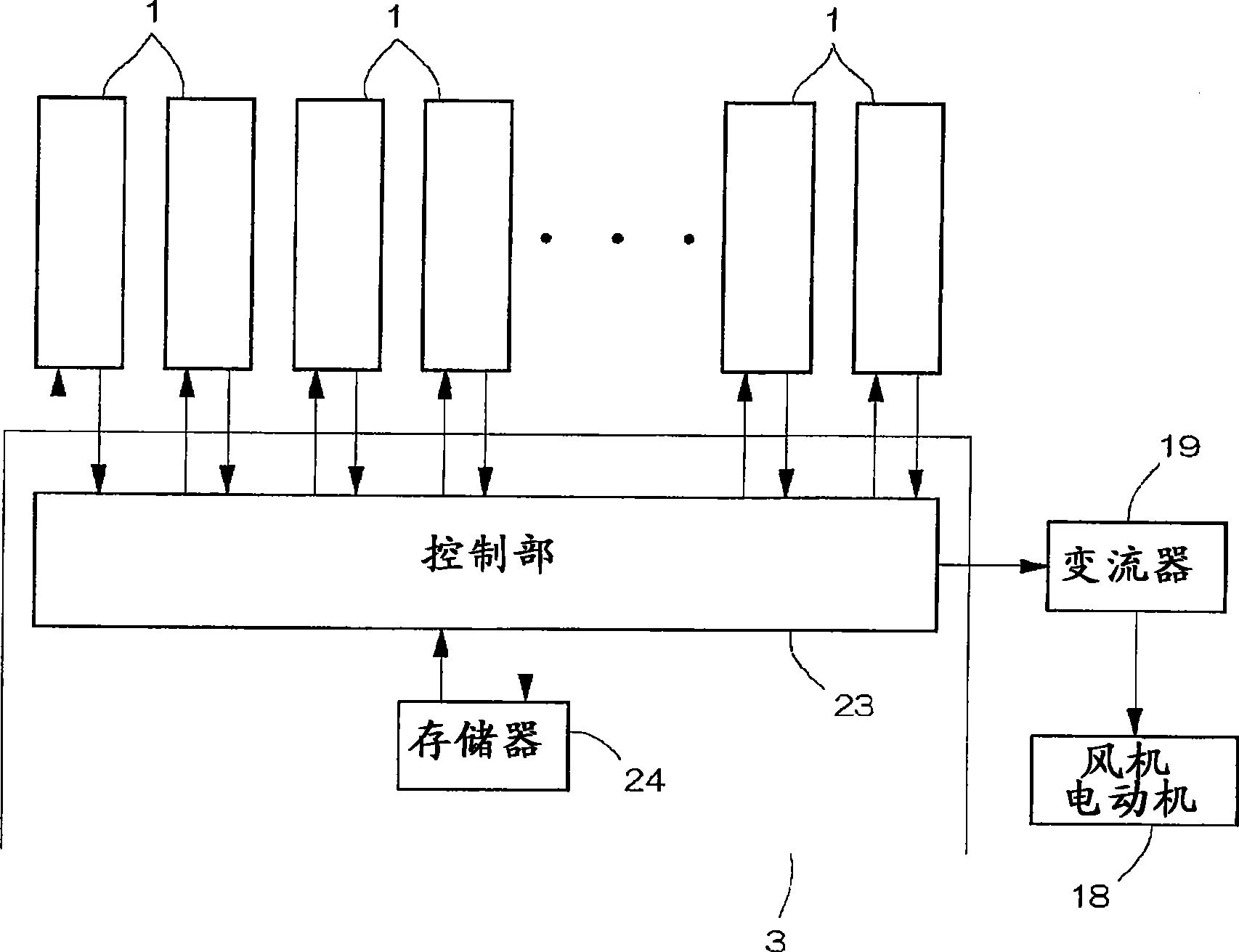
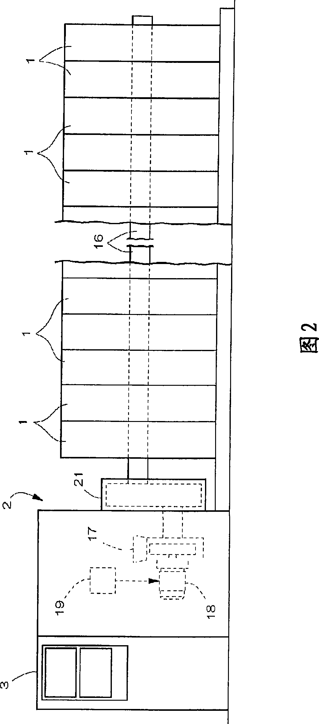
[0025] based on Figure 1 to Figure 4A first embodiment of an automatic winding machine to which the fan motor control method according to the present invention is applied will be described. As shown in Figure 2, the automatic winding machine includes: a group of winding units 1 configured in a row, a fan system 2 for supplying negative pressure to each winding unit 1, and a set of winding units 1 and the fan system. A control device 3 that performs operation management of the system 2 .

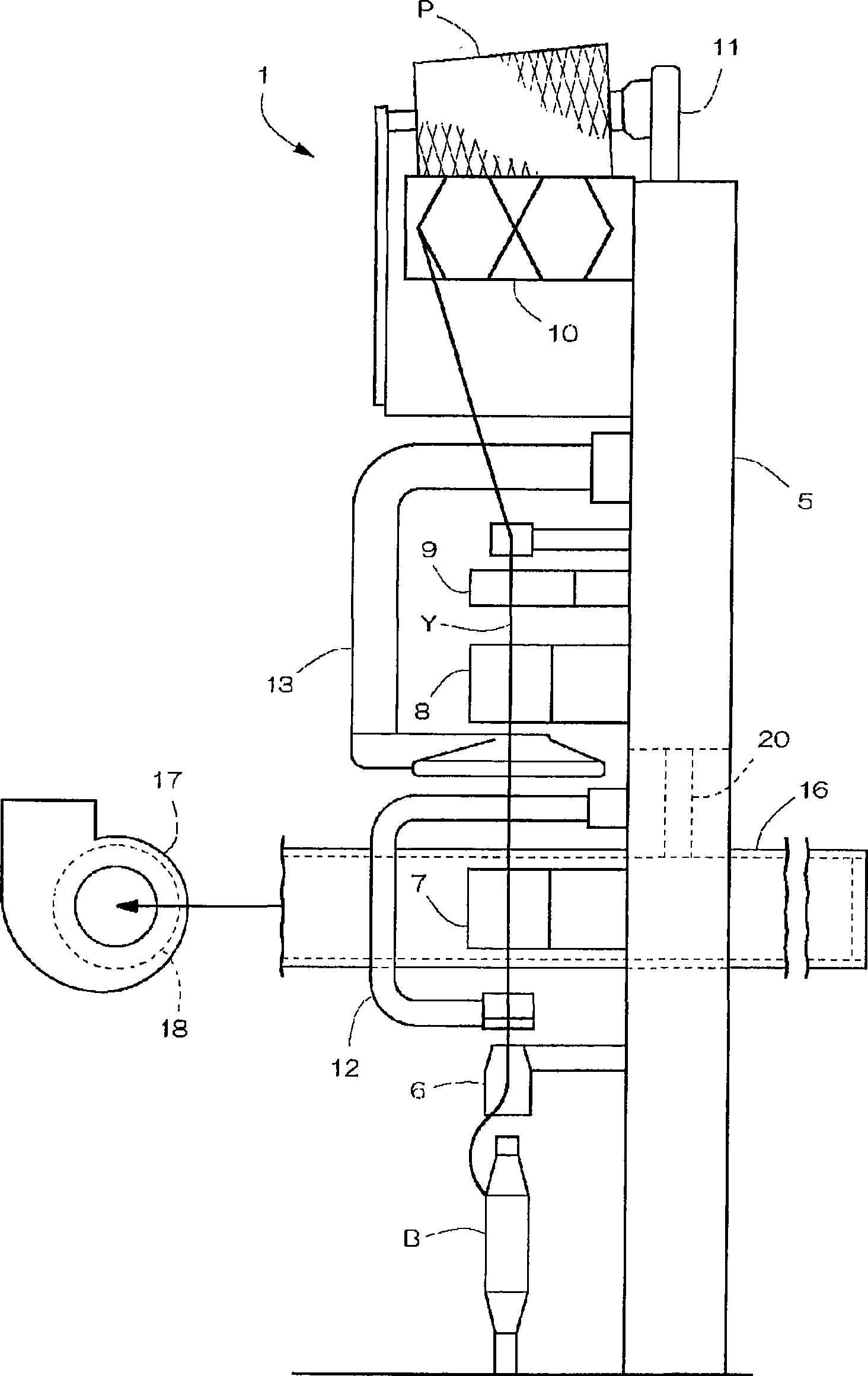
[0026] image 3 Among them, the winding unit 1 is constructed with a vertically long box-shaped main body frame 5 fixed upright as a base. The balloon breaker 6, the tension device 7, the piecing device 8, the yarn clearer 9, etc. are arranged on one side of the main frame 5 in the order described above from the lower part of the frame to the upper part of the frame. On one side of the upper part of the main body frame 5 are arranged a reciprocating drum 10 for moving and operating the ya...


PUM


Abstract

The present invention enables the rotation speed of a motor driving a blower to be controlled without the need for an additional device such as a sensor. The present invention enables the rotation speed of the motor driving the blower to be controlled while supplying a minimum required negative pressure. The present invention thus saves required energy while smoothly operating an automatic winder. The number of yarn splicing operation in each winding unit 1 and the number of failures in yarn splicing are counted to calculate the mistake rate of the whole system. On the basis of the calculated mistake rate, the output frequency of an inverter (19) supplying power to the blower motor (18) is controllably increased or reduced.

Description

technical field [0001] The present invention relates to a control method and a fan system for a fan motor that supplies negative pressure to a plurality of winding units constituting an automatic winding machine. Background technique [0002] The winding unit of the automatic winding machine for winding the yarn unwound from the yarn supply bobbin to form a package is equipped with cutting the yarn when a yarn defect is detected to remove the yarn defect and perform automatic piecing connector function. In the yarn joining operation described above, the upper yarn end on the package side is caught by the negative pressure (suction force) supplied to the suction nozzle. Then, the upper yarn end is delivered to the yarn joining device by the suction nozzle. Therefore, in an automatic winding machine in which a plurality of winding units are arranged in parallel, it is necessary to supply a negative pressure to each winding unit. Therefore, a fan system that supplies negativ...

Claims


Application Information

Patent Timeline
Patent Type & Authority Applications(China)
IPC IPC(8): G05D16/14B65H67/08B65H63/06B65H54/70H02P27/04F04D25/06F04D27/00D01H15/00
CPCB65H54/26B65H54/70B65H2701/31B65H69/061
Inventor 须佐见浩之
Owner MURATA MASCH LTD
Why Eureka
Try Eureka