
Signal processing method, system and optical line terminal

A signal processing and signal technology, applied in the field of optical network, can solve problems such as signal quality degradation, achieve the effect of improving signal quality and reducing crosstalk

Inactive Publication Date: 2009-04-29
贾俊玲
View PDF0 Cites 8 Cited by
  • Summary
  • Abstract
  • Description
  • Claims
  • Application Information

AI Technical Summary

Problems solved by technology

This will inevitably lead to a decrease in the signal quality after power amplification
However, there is no signal processing method in the prior art that can well improve the problems of signal-to-noise ratio reduction and crosstalk noise when the existing PON network equipment and NGA network equipment coexist, thereby improving the quality of the signal after power amplification

Method used


Image

  • Signal processing method, system and optical line terminal
  • Signal processing method, system and optical line terminal
  • Signal processing method, system and optical line terminal

Examples


Embodiment Construction

[0025] In order to make the objectives, technical solutions, and advantages of the present invention clearer, the present invention will be described in detail below with reference to the accompanying drawings and specific embodiments.

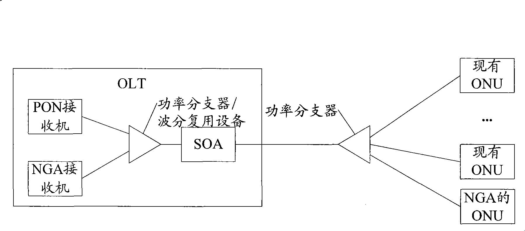
[0026] For convenience, in the following description, the ONU of the existing PON network is referred to as the existing ONU, and the ONU of the NGA network is referred to as the ONU of the NGA.

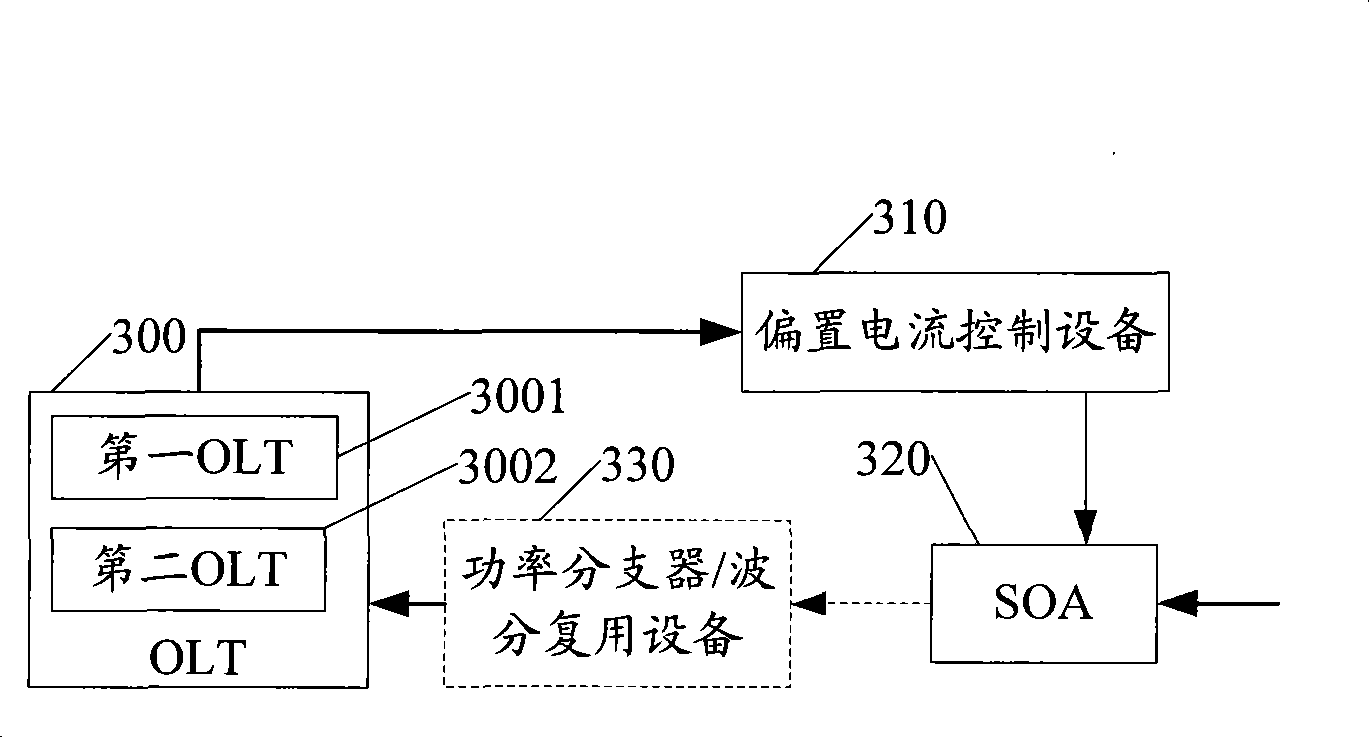
[0027] The method provided by the embodiment of the present invention mainly includes: obtaining bandwidth authorization information for the next time period allocated to each ONU; adjusting the bias current of the SOA in the next time period according to the obtained bandwidth authorization information, so that the SOA is paired with signals passing through the SOA The resulting gain satisfies the set conditions; the SOA performs power amplification on the received signal.

[0028] Figure 3a It is a system structure diagram provided by an embodiment o...


PUM


Abstract

The present invention provides a method for processing signal, a system and an optical line terminal thereof. The bandwidth authorization information of next time period distributed for each optical network unit (ONU) is obtained. The offset current of a semiconductor optical amplifier (SOA) is regulated at the next time period according to the obtained bandwidth authorization information. The SOA is leaded to be satisfied to the set condition to the gain generated by the signal passing through the SOA. The SOA executes power amplification to the received signal. The signal transmission stateof each ONU at the next time period can be obtained through the obtained bandwidth authorization information. The offset current of SOA is dynamically adjusted according to the signal transmission state of each ONU thereby causing that the gain generated by SOA is satisfied for the preset condition. Thereby the signal quality after power amplification can be increased when the existing passive optical network (PON) device and the next generation access (NGA) network device coexist.

Description

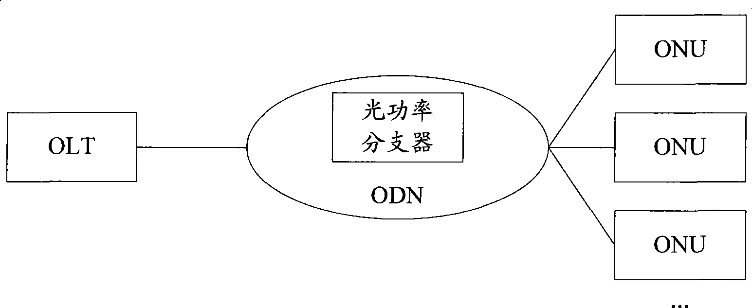
Technical field [0001] The present invention relates to optical network technology, in particular to a signal processing method, system and optical line terminal. Background technique [0002] As the cost of passive optical network (PON, Passive Optical Network) has dropped significantly, PON has gradually become the best choice for operators to solve the last-mile problem. At present, the main PON technology is based on Time Division Multiplex (TDM), such as broadband passive optical network (BPON, Broadband PON), Ethernet passive optical network (EPON, Ethernet BasedPON), Gigabit passive Optical network (GPON, Gigabit-capable PON), etc. [0003] TDM-based PON (TDM-PON) technology is a point-to-multipoint optical access technology. figure 1 It is the structure diagram of the TDM-PON system in the prior art, such as figure 1 As shown, the TDM-PON system mainly includes: an optical line terminal (OLT, Optical Line Terminator) placed in the operator’s central office (CO, Central ...

Claims


Application Information

Patent Timeline
IPC IPC(8): H04L29/02H04L12/24
Inventor 林华枫喻凡
Owner 贾俊玲
Learn More