

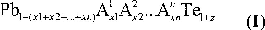
Doped lead tellurides for thermoelectric applications
A thermoelectric and compound technology, applied in selenium/tellurium compounds, metal selenide/telluride, thermoelectric device junction lead wire materials, etc., can solve problems such as reducing specific thermal conductivity
- Summary
- Abstract
- Description
- Claims
- Application Information
AI Technical Summary
Problems solved by technology
Method used
Image

Examples
example 1
[0108] Element powder in quantity according to composition Pb 0.992 Ge 0.005 Ti 0.003 Te 1.003 (Purity: Pb≥99.999%, Te≥99.999%, Ge≥99.999%, Ti≥99.99%) were weighed into a quartz ampoule with an inner diameter of 1 cm. The amount of the sample is 20 g. Evacuate and seal the ampoule. Subsequently, the ampoule is 500Kh in the furnace -1 It was heated to 980° C. and kept at this temperature for 6 h. The contents of the ampoules were continuously mixed by tilting the furnace. After the reaction time, the shaft furnace is at 100Kh -1 was cooled to 600 °C and the material was heat-treated at this temperature for 24 h. Subsequently, the furnace is at 60Kh -1 was cooled to room temperature.
[0109] A compact, silvery slag was obtained, which could be removed from the ampoule without any problems. A diamond wire saw was used to cut approximately 2 μm thick slices from metal slag, on which first the electrical conductivity and then the Seebeck coefficient were measured at roo...
example 2
[0112] Element powder in quantity according to composition Pb 0.992 Ge 0.005 Ti 0.003 Te 1.003 (Purity: Pb≥99.999%, Te≥99.999%, Ge≥99.999%, Zr≥99.95%) were weighed into a quartz ampoule with an inner diameter of 1 cm. The amount of the sample is 20 g. Evacuate and seal the ampoule. Subsequently, the ampoule is 500Kh in the furnace -1 It was heated to 980° C. and kept at this temperature for 6 h. The contents of the ampoules were continuously mixed by tilting the furnace. After the reaction time, the shaft furnace is at 100Kh -1 was cooled to 600 °C and the material was heat-treated at this temperature for 24 h. Subsequently, the furnace is at 60Kh -1 was cooled to room temperature.
[0113] A compact, silvery slag was obtained, which could be removed from the ampoule without any problems. A diamond wire saw was used to cut approximately 2 mm thick slices from metal slag, on which first the electrical conductivity and then the Seebeck coefficient were measured at roo...
example 3
[0116] Element powder in quantity according to composition Pb 0.99 Bi 0.005 al 0.005 Te 1.001 (Purity: Pb≥99.999%, Te≥99.999%, Al≥99.999%, Bi≥99.998%) were weighed into a quartz ampoule with an inner diameter of 1 cm. The amount of the sample is 20 g. Evacuate and seal the ampoule. Subsequently, the ampoule is 100Kh in the furnace -1 It was heated to 1000° C. and kept at this temperature for 15 h. The contents of the ampoules were continuously mixed by tilting the furnace. After the reaction time, the shaft furnace was switched off and allowed to cool to room temperature.
[0117] A compact, matt silver-shiny slag was obtained which could be removed from the ampoule without any problems. A diamond wire saw was used to cut approximately 2 mm thick slices from metal slag, on which first the electrical conductivity and then the Seebeck coefficient were measured at room temperature.
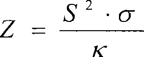
[0118] Corresponds to S 2 σ=23.7μWK -2 cm - 1 power factor, conductivity is σ=992.0S ...
PUM
| Property | Measurement | Unit |
|---|---|---|
| Conductivity | aaaaa | aaaaa |
| Seebeck coefficient | aaaaa | aaaaa |
| Conductivity | aaaaa | aaaaa |
Abstract
Description
Claims
Application Information