
Vertebra filling block

A technology of spinal filling block and cushion body, which is applied in spinal implants, medical science, internal bone synthesis, etc., can solve problems such as damage to spinal joints, and achieve the effect of reducing wear consumption, increasing service life, and assembling stably

Inactive Publication Date: 2009-05-06
TOPASIA INT TECH INC
View PDF0 Cites 1 Cited by
  • Summary
  • Abstract
  • Description
  • Claims
  • Application Information

AI Technical Summary

Problems solved by technology

[0003] The main purpose of the present invention is to improve the aforementioned problems of the prior art, and provide a spinal filling block with elastic deformation capacity, which can be installed between two adjacent vertebral body endplates of the human spine to reconstruct the original shape of the collapsed intervertebral disc. High, eliminate the compression on the spinal cord or nerve root, and at the same time provide the natural mobility and range of motion of the intervertebral disc at the treatment site through its elastic cushioning properties, so it must work closely with other normal intervertebral discs to maintain the original space between the upper and lower vertebrae The performance provided by the joint can avoid damage to the upper and lower vertebral joints. Furthermore, after a period of time after installation, the upper and lower pads of the spine filler can be respectively consolidated into one body with the upper and lower vertebrae, thereby increasing the stability of the installation and avoiding Misalignment or loosening of implants prevents loss of excessive anteversion in spinal motion

Method used


Image

  • Vertebra filling block
  • Vertebra filling block
  • Vertebra filling block

Examples


Embodiment Construction

[0029] The other objectives, advantages and notable features of the present invention will be described below, and the present invention can be realized after being familiar with the technology and reading the description in the text.

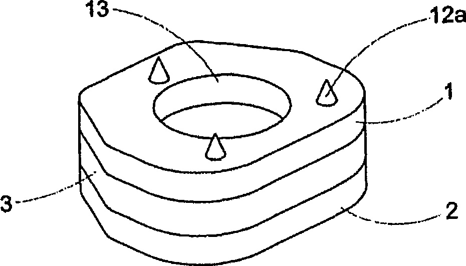
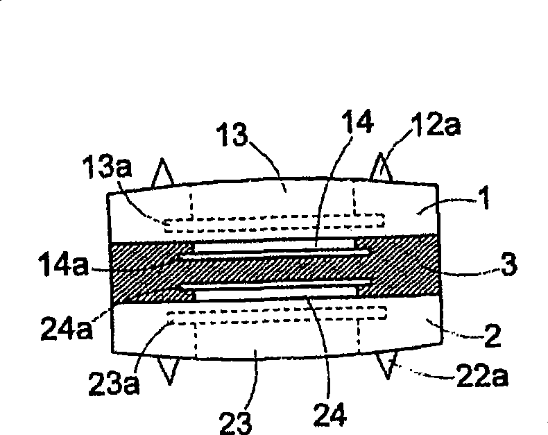
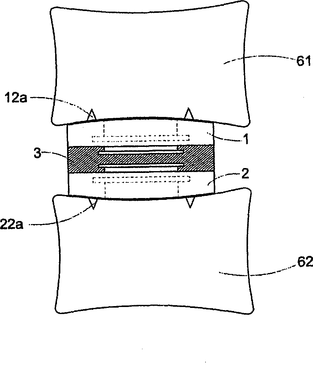
[0030] Please refer to the attached figures, which are preferred embodiments of the spinal filling block of the present invention, and its composition mainly includes an upper cushion body 1, a lower cushion body 2 and an elastic body 3; wherein,

[0031] The upper pad body 1 is made of composite materials (such as carbon fiber, polyether ether ketone, PEEK-polyether ether kefone, etc.) or alloy materials (such as titanium alloy, stainless steel, etc.), so it has good mechanical strength and Chemical resistance, suitable for use between human spines; make the top surface of the pad body a slightly convex arc surface, which can just conform to the concave arc configuration of the bottom end surface of the vertebral block 61 to be installed; The ...


PUM


Abstract

The invention discloses a spinal filling block which comprises an upper padding body, a lower padding body and an elastomer; the top surface of the upper padding body is provided with a slip stopping structure and at least one bone grafting pit, and the bottom surface of the upper padding body is convexly provided with at least one rabbet-joint column, wherein, the outer diameter of the lower part of the rabbet-joint column is larger than that of the higher part; the bottom surface of the lower padding body is provided with a slip stopping structure and at least one bone grafting pit, and the top surface of the lower padding body is convexly provided with at least one rabbet-joint column, wherein, the outer diameter of the lower part of the rabbet-joint column is larger than that of the higher part; and the elastomer is arranged between the upper padding body and the lower padding body and used for tightly wrapping, covering and integrating the rabbet-joint column on the bottom surface of the upper padding body and the rabbet-joint column on the top surface of the lower padding body. The flexibility and buffering property of the spinal filling block are utilized to provide natural mobility and motion range for intervertebral disc of location to be treated, maintain the efficiency provided by an original joint between an upper vertebra and a lower vertebra and prevent the injury of the joint between the upper vertebra and the lower vertebra. After being installed for a period, the upper padding body and the lower padding body of the spinal filling block are respectively consolidated with the upper vertebra and the lower vertebra, thus strengthening the fixedness.

Description

technical field [0001] The invention relates to a vertebra filling block, in particular to a vertebra filling block which is used as an artificial intervertebral disc for installation between two adjacent vertebral body end plates of the human spine. Background technique [0002] The spine in the human skeleton extends downward from the medulla to the thigh. There are many nerves in the spine, and it is formed by the connection of several vertebrae. There is an intervertebral disc between the upper and lower adjacent vertebrae, and the intervertebral disc It is a delicate structure that is quite in line with the mechanical principle. It is shaped like a disc. There is a nucleus pulposus in the center of the intervertebral disc. It is almost a water ball made of pure liquid. It has considerable plasticity and can absorb the vertical pressure of the spine. It is composed of multi-layered fibrous rings. The strong structure can maintain the stability of the nucleus pulposus. Th...

Claims


Application Information

Patent Timeline
IPC IPC(8): A61F2/44A61B17/70A61L27/14
CPCA61F2/44A61F2002/30001
Inventor 颜宗宝
Owner TOPASIA INT TECH INC
Learn More