PDLC grating of lcd equipment and making method

A technology of liquid crystal display and manufacturing method, which is applied in the direction of optomechanical equipment, chemical instruments and methods, optics, etc., can solve the problems of affecting the use effect of PDLC grating 11, blurring of liquid crystal display images, and insufficient transparency, so as to eliminate blurring and improve Display quality, effect of improving transmittance

Active Publication Date: 2009-05-06
BYD CO LTD
View PDF0 Cites 28 Cited by
  • Summary
  • Abstract
  • Description
  • Claims
  • Application Information

AI Technical Summary

Problems solved by technology

[0005] In the process of forming the PDLC grating 11 (that is, during the process of the ultraviolet light 12 irradiating the PDLC grating 11 through the mask plate 10), along with the continuous polymerization of the polymerized monomer in the light-transmitting region 115, the polymerized monomer in the opaque region 114 The polymerization reaction cannot be completely transferred to the light-transmitting region 115, and the liquid crystal 120 is not completely present in the light-impermeable region 114, and a little polymer 121 is bound to remain, so the light-impermeable region 114 becomes not transparent enough, affecting the PDLC grating 11 The effect of using it, so it will produce blurring in the LCD image

Method used


Image

  • PDLC grating of lcd equipment and making method
  • PDLC grating of lcd equipment and making method
  • PDLC grating of lcd equipment and making method

Examples


Embodiment Construction

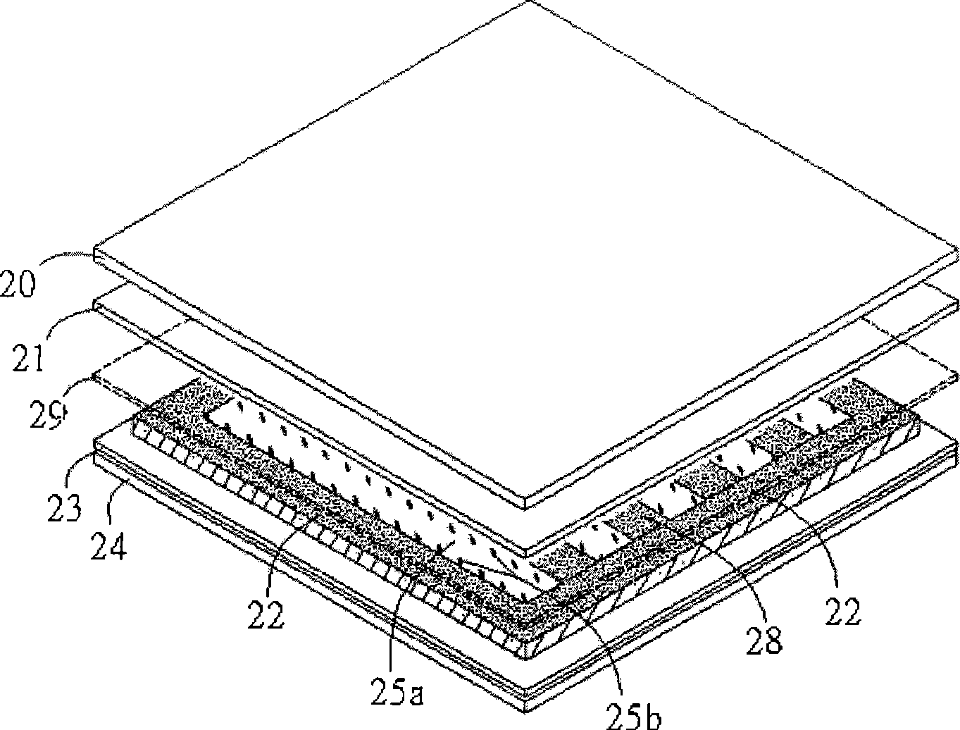
[0036] like figure 2 The PDLC grating of the liquid crystal display device of the embodiment of the present invention is shown, including: a first substrate 24, a first electrode layer 23, a second substrate 20, a second electrode layer 21, a grid-like photoresist spacer 28, and a polymer 25a , the liquid crystal droplet 25b and the frame 22.

[0037] Wherein the first electrode layer 23 is placed on the upper surface of the first substrate 24, and the second electrode layer 21 is placed on the lower surface of the second substrate 20. The material of the first electrode layer 21 and the second electrode layer 20 can be selected from ITO (indium tin oxide) Grid-shaped photoresist spacers 28 are located between the first electrode layer 23 and the second electrode layer 21, and liquid crystal droplets 25b and polymers 25a are distributed between adjacent grid-shaped photoresist spacers 28.

[0038] The working principle of this embodiment: when an electric field is applied betw...


PUM

PropertyMeasurementUnit
thicknessaaaaaaaaaa

Abstract

The invention discloses a PDLC raster and a manufacture method of an LCD device, wherein the raster structurally comprises a first base plate, a second base plate, a first electrode layer and a second electrode layer, the first electrode layer is arranged on the upper surface of the first base plate, the second electrode layer is arranged on the lower surface of the second base plate, and PDLC material is infused in a palisade groove formed by a palisade light resistance insulating object to be disposed to a polymer and liquid crystal droplets which are arranged between the first electrode layer and the second electrode layer. When an electric field is applied, the PDLC raster presents a full transparent state; when the electric field is not applied, the PDLC raster forms a light shield slit and a light transmission slit and presents the raster characteristic, thus, two display functions of the transparent display state and the raster characteristic can be realized in the way that the electricity is applied or not applied, the consuming quantity of the polymer and liquid crystal can be saved, the manufacture process is simplified, and the LCD quality can be improved simultaneously.

Description

technical field [0001] The general concept of the present invention relates to a liquid crystal display device, in particular to a PDLC (Ploymer Dispersed Liquid Crystal) grating with an improved structure and a manufacturing method thereof. Background technique [0002] With the continuous development of liquid crystal technology, liquid crystal gratings are being studied extensively and deeply. Since this device has electric field controllability, it has a good application prospect in the fields of diffractive optics, projection display, optical switch and so on. However, the manufacture of liquid crystal devices requires many special processes, such as orientation treatment of liquid crystal molecules, control of cell thickness, sealing of cells, patching, etc., which complicates the manufacturing process and increases the manufacturing cost. The PDLC grating, through the electric field to adjust the refractive index of the liquid crystal, realizes the light scattering i...

Claims


Application Information

Patent Timeline
Patent Type & Authority Applications(China)
IPC IPC(8): G02F1/1333G02F1/1343G03F7/00B32B37/12
Inventor 王志国陈学刚
Owner BYD CO LTD
Why Eureka
Try Eureka