
Current collection body for battery

A battery collector and conductor nail technology, applied in the direction of electrode carrier/current collector, small-sized battery/battery pack, battery box/jacket, etc., can solve the problems of reduced battery reliability, poor reliability, uneven density of sealing rings, etc. , to achieve the effect of increasing the capacitance, reducing the thickness, and filling the space with large active materials

Active Publication Date: 2009-05-06
ZHONGYIN NINGBO BATTERY CO LTD
View PDF0 Cites 11 Cited by
  • Summary
  • Abstract
  • Description
  • Claims
  • Application Information

AI Technical Summary

Problems solved by technology

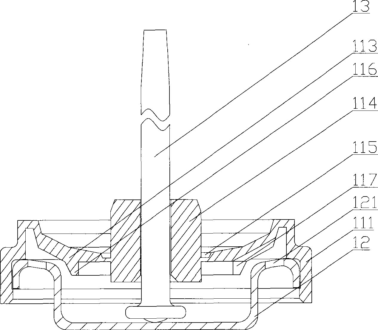
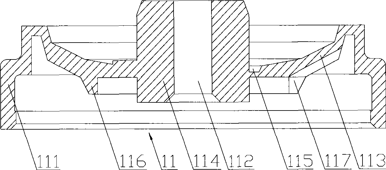
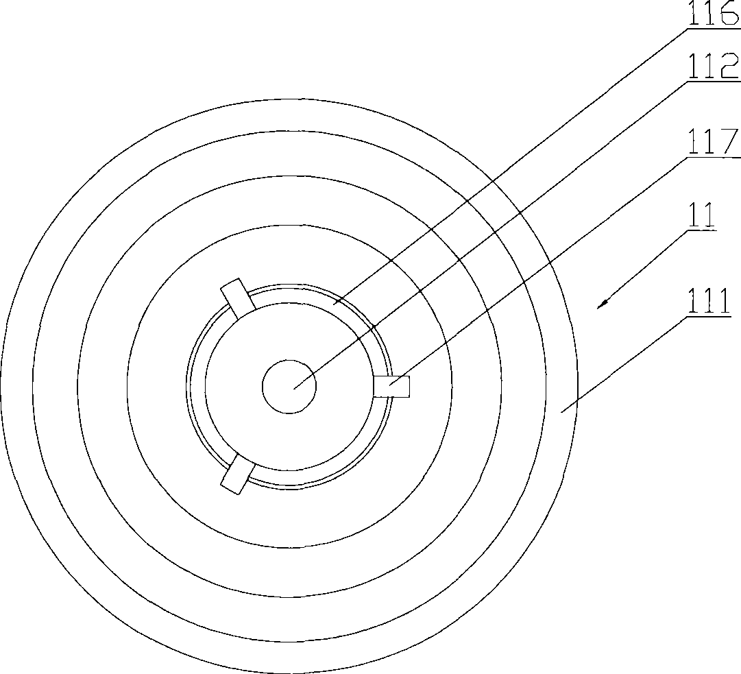
[0010] However, the existing sealing rings are usually processed by radial injection molding process. During the injection molding process, the injection molding material diverges and flows from its center to the surroundings. The above-mentioned air guide ports 117 existing between the raised structures 116 will locally change the injection molding process in the mold. The radial flow direction of the material leads to uneven density of the formed sealing ring
However, the mass distribution of the sealing ring 11 is required to achieve a relatively high degree of uniformity. The reason is that the uneven density will lead to problems such as easy cracking and brittleness of the sealing ring, which will significantly shorten its service life and may cause liquid leakage. reduce battery reliability
Current collectors in the prior art cannot overcome this contradiction, and the service life of the sealing ring must be short and the reliability must be poor

Method used


Image

  • Current collection body for battery
  • Current collection body for battery
  • Current collection body for battery

Examples


Embodiment Construction

[0037] The core of the invention is to provide a battery collector capable of prolonging the service life and reliability of the sealing ring while ensuring the safety and explosion-proof performance of the battery.

[0038] In order to enable those skilled in the art to better understand the solution of the present invention, the present invention will be further described in detail below in conjunction with the accompanying drawings and embodiments.

[0039] see Figure 4 and Figure 5 , Figure 4 It is a structural schematic diagram of a specific embodiment of the sealing ring provided by the present invention; Figure 5 for Figure 4 Bottom view of the seal shown.

[0040] In a specific implementation manner, the sealing ring 21 provided by the present invention can be made of nylon material, specifically, nylon 6, nylon 66 or nylon 610 can be selected.

[0041] The sealing ring 21 comprises a generally annular main plane 213 which is perpendicular to the longitudinal a...


PUM


Abstract

The invention discloses a battery collector body. A sealing ring thereof is a rotating body; the bottom cover of the rotating body is provided with a raised structure protruding towards the sealing ring; and a deflation hole on the bottom cover is arranged in the raised structure. The raised structure is used for supporting the sealing ring when the sealing ring falls down due to a broken explosion-proof channel, thereby a broken opening communicated with the sealing ring and a deflation channel of the deflation hole are formed. Because the sealing ring is the rotating body, the mass distribution of the sealing ring is more uniform during the injection mold and processing, thereby the problem that the sealing ring is friable and easily broken in the prior art is effectively avoided, the service life is prolonged, and the reliability is improved. Because the deflation hole is arranged in the raised structure and is not on an identical plane with the bottom surface of the bottom cover, the tail end of a holddown spring is not easy to extend. In addition, because the thickness of the sealing ring is relatively lowered, the inside of the battery is ensured to have a larger space filled with active substances, thereby the capacitance of the battery is obviously improved.

Description

technical field [0001] The invention relates to the field of battery sealing and explosion protection, in particular to a battery current collector structure. Background technique [0002] The current collector is an important structure in the battery, and its functions mainly include three aspects: one is to collect and transmit the current generated by the negative part of the battery inside; the other is to seal, that is, to close the opening at the bottom of the battery case; the third is to prevent explosions , to prevent the battery from exploding due to its internal gas pressure being too high. [0003] Please refer to figure 1 , figure 2 as well as image 3 , figure 1 It is a structural schematic diagram of a battery current collector in the prior art; figure 2 for figure 1 Schematic diagram of the structure of the sealing ring in the current collector shown; image 3 for figure 2 Bottom view of the seal shown. [0004] The current collector usually inclu...

Claims


Application Information

Patent Timeline
Patent Type & Authority Applications(China)
IPC IPC(8): H01M2/08H01M2/12H01M2/30H01M4/64H01M50/184H01M50/186H01M50/342H01M50/543
CPCY02E60/12Y02E60/10
Inventor 谢红卫王静峰
Owner ZHONGYIN NINGBO BATTERY CO LTD
Learn More