Contact lens molding method and mould

A technology of contact lenses and molding methods, which is applied to household appliances, types of packaging items, and other household appliances, and can solve problems such as cumbersome processing steps, long processing time, and difficult manufacturing processes

Inactive Publication Date: 2009-05-13
UNICON OPTICAL
View PDF0 Cites 9 Cited by
  • Summary
  • Abstract
  • Description
  • Claims
  • Application Information

AI Technical Summary

Problems solved by technology

[0004] (1) The manufacturing method of the turning method must inject liquid material into the glass tube, harden it at high temperature, cut it into a circular sheet by the wheel, and turn, grind and polish it, and then soak the lens in the buffer Soften it in liquid, the manufacturing process is cumbersome, time-consuming and labor-intensive, if a mistake is made in any step, it will become a defective product, and the process cannot be continued, which will also increase the defective rate of the product
[0005] (2) The mold casting method is to inject the liquid material into the middle of the two molds, use the pressing of the two molds, and then heat and heat up the liquid material to harden the liquid material, and then soak the lens in the buffer solution after edging and polishing To soften it for subsequent packaging operations, but the manufacturing process is long and the processing steps are cumbersome, time-consuming and labor-intensive, and there are many processing steps in the processing process, which will easily increase the defective rate of the product and relatively increase the manufacturing cost
[0006] (3) The rotary mold method is to inject the liquid material into the rotating optical mold for mirror making, and through the centrifugal force generated by the optical mold for mirror making when it rotates, the liquid material is evenly spread on the inner wall of the optical mold for mirror making, and through Ultraviolet light irradiates the liquid material to harden and form it in the m...

Method used


Image

  • Contact lens molding method and mould
  • Contact lens molding method and mould
  • Contact lens molding method and mould

Examples


Embodiment Construction

[0053] In order to achieve the above purpose and effect, the technical means and structure adopted by the present invention will be described in detail with reference to the accompanying drawings for the preferred embodiments of the present invention. Its features and functions are as follows for complete understanding.

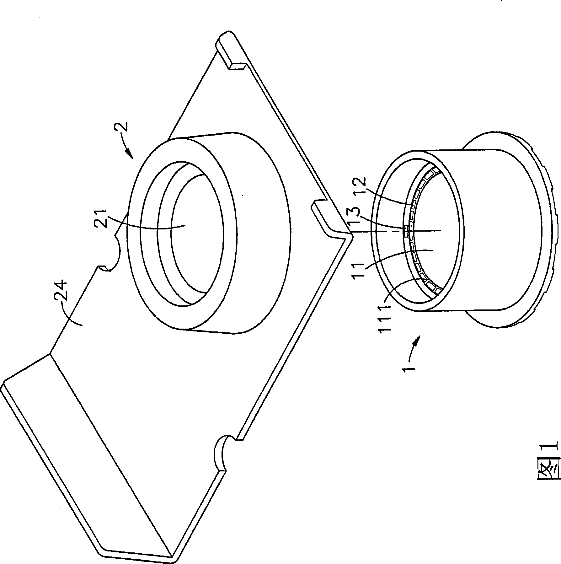
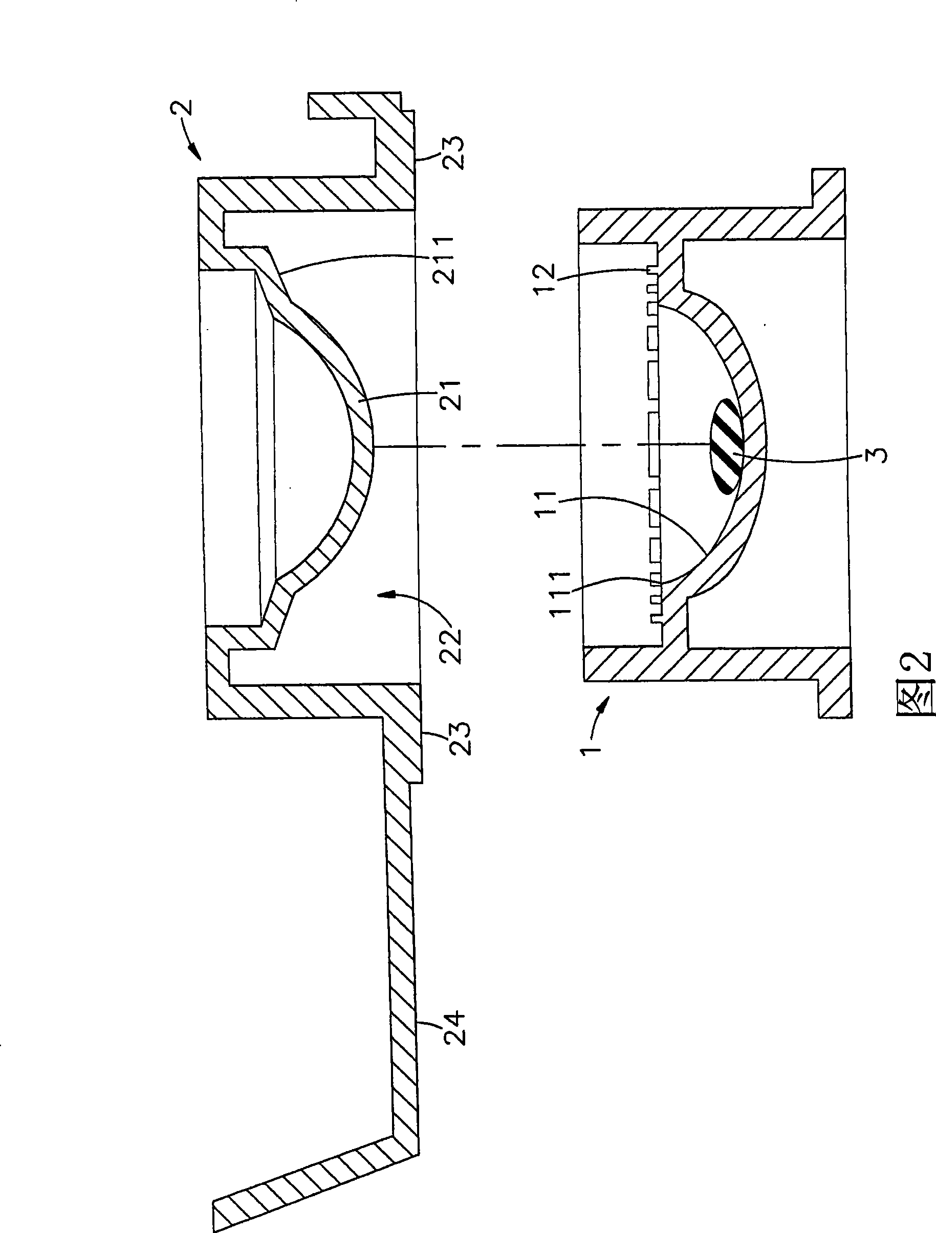
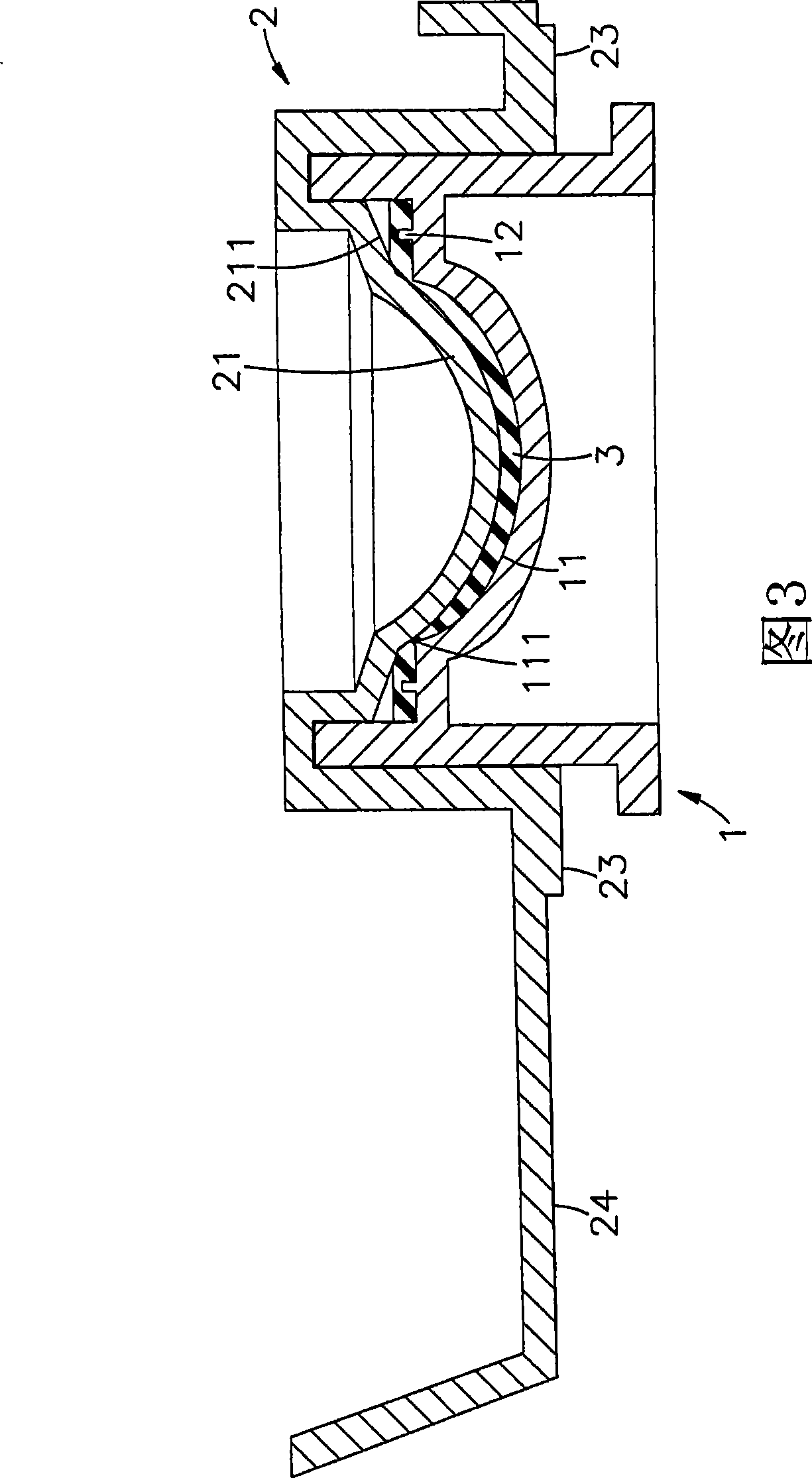
[0054] Please refer to shown in Fig. 1, 2, 3, it is three-dimensional exploded view, side view disassembled sectional view, side view sectional view of the present invention, can clearly find out by shown in the figure, the forming method and mold of contact lens of the present invention, It includes a mold 1 and an auxiliary device 2, wherein:

[0055] The inside of the mold 1 is concavely provided with a mold cavity 11, and the mold cavity 11 is in the shape of an arc surface, and a sharp corner-cutting edge 111 is formed on the outer periphery of the top, and on the periphery of the corner-cutting edge 111, the ring is provided with A plurality of micro-pr...


PUM


Abstract

The invention relates to a method for shaping contact lenses and a mould, particularly a method which can use simple moulds for forming the contact lenses. The method comprises the following steps: placing the contact lens material in a die cavity of a mould; then, using the mould of an auxiliary appliance to press the lens material in the die cavity; causing the lens material to spread and extend along an arc surface of a die cavity and a mould; pushing excessive materials and overflowing out of the corner cut edge; proving the retained surface at the outer part of the mould for jointing the corner cut edge; removing the excessive materials; solidifying and treating the lens material in the mould; jointing the lens material on the surface of the mould of the auxiliary appliance; shaping glasses of the contact lenses after testing; packaging after injecting buffer solution in the appliance space of the outer part of the mould of an auxiliary appliance; and manufacturing products for selling. The contact lens has the advantages that the manufacturing procedure is simple and fast; and the purposes for saving labor and time, reducing the manufacturing cost, and keeping with the economic effect can be achieved.

Description

technical field [0001] The invention relates to a molding method and mold for contact lenses, especially a method for molding and processing contact lenses by using simple molds, using auxiliary equipment and molds to cooperate with the processing operations, so that the contact lenses can be attached to the auxiliary equipment for packaging. Sales, and can shorten the processing process to achieve the purpose of saving time and labor. Background technique [0002] The idea of ​​wearing lenses directly on the eyes was proposed by Da Vinci as early as 1508, and Descartes (RENE Descartes) also made a similar suggestion in 1636. In 1887, the German scientist Adolf Eugen Fick successfully created the first However, due to its low oxygen permeability, it is easy to cause eye diseases such as keratitis; in modern times, in 1938, Mullen and Obring made the first pair of all-plastic contact lenses by using PMMA as the material; and in 1940 Obring, located in New York, USA, develope...

Claims


Application Information

Patent Timeline
IPC IPC(8): B29D11/00B29C43/02B29C43/40B29C43/36B29C43/20B29C43/18B65B25/00B65D81/00B65D81/15B65D85/00B65D85/30B65B55/22
Inventor 陈正修
Owner UNICON OPTICAL
Why Eureka
Try Eureka