Mould apparatus and method for manufacturing multicomponent glass optical fiber prefabricating stick
A glass optical fiber and preform technology, applied in glass manufacturing equipment, manufacturing tools, etc., can solve the problems of large interface loss, complex manufacturing process, and difficulty in manufacturing glass optical fibers with special end-face structure, so as to reduce impurity and bubble loss, and reduce the loss of impurities and bubbles. Simple and easy, avoid the effect of glass rod burst
- Summary
- Abstract
- Description
- Claims
- Application Information
AI Technical Summary
Problems solved by technology
Method used
Image
Examples
Embodiment 1
[0035] A method for preparing a single-mode optical fiber preform, comprising the steps of: comprising the steps of:
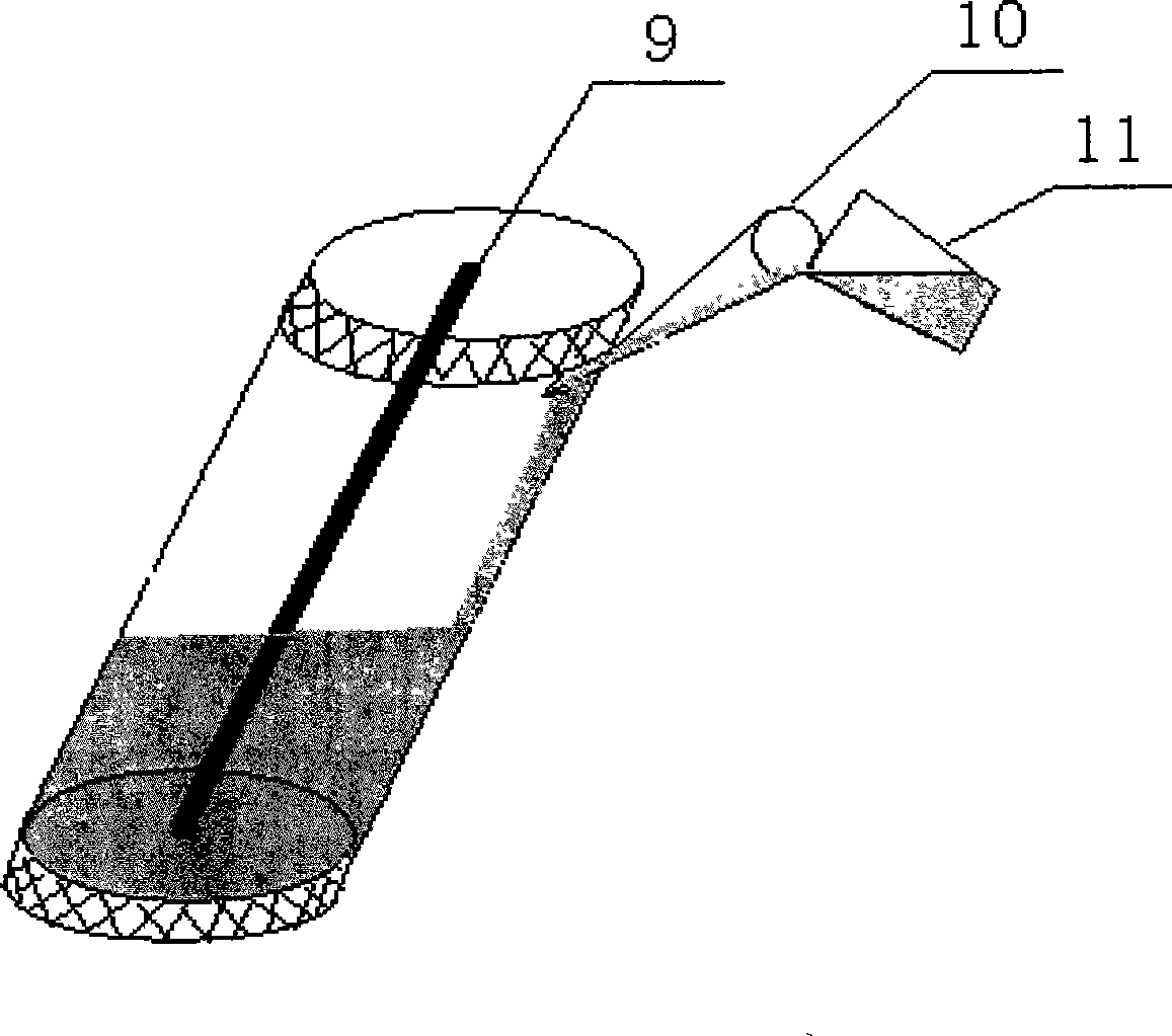
[0036]①Melting the core glass and making it into a round rod, draw it into a core glass rod 9 with a diameter of 1.2mm according to the required shape and size of the fiber core by an optical fiber drawing machine;
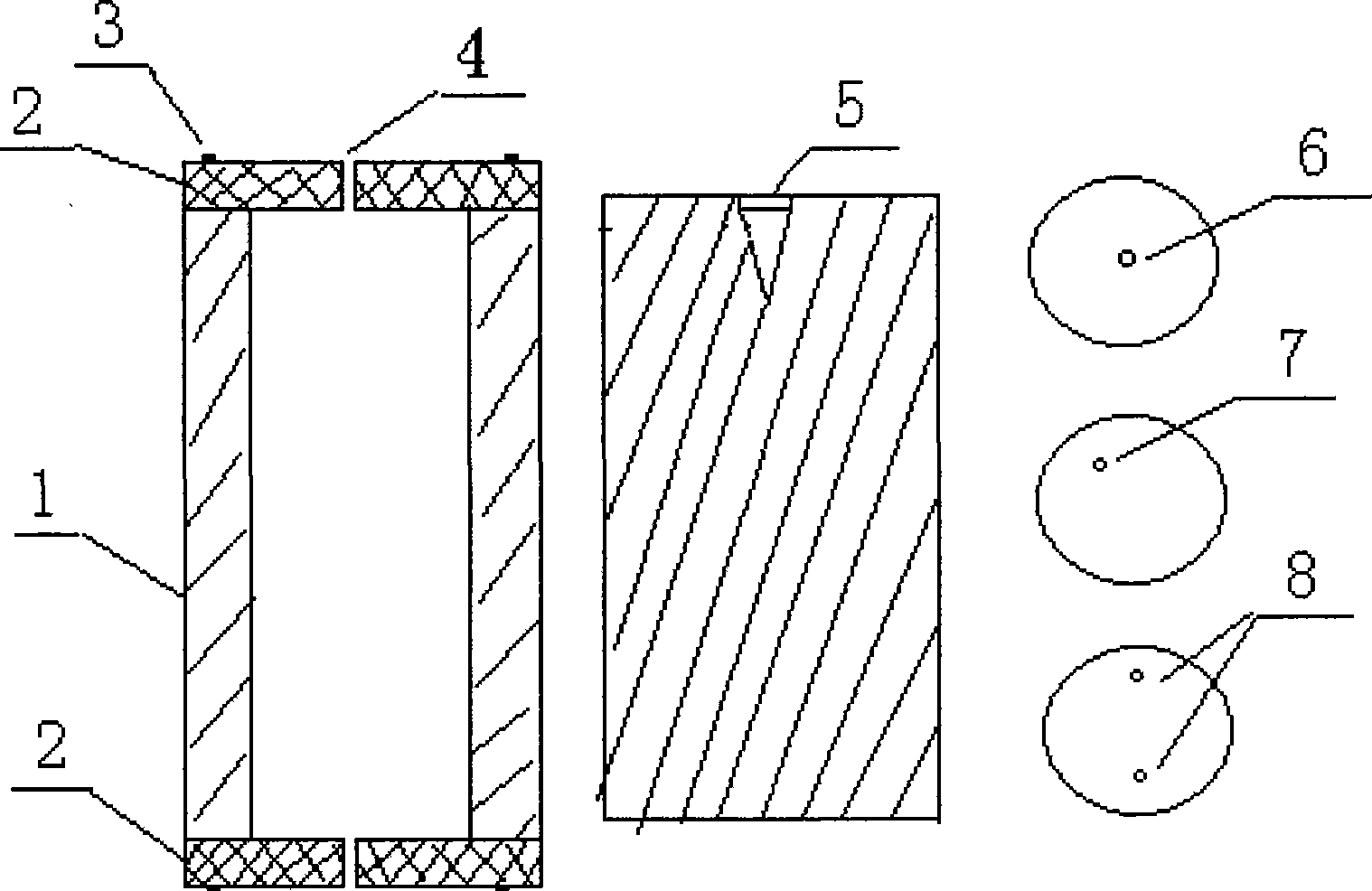
[0037] ②According to the structure and size of the multi-component glass optical fiber, select or process the required mold device, including the length and inner diameter of the stainless steel cylindrical cylinder 1, the number, shape and position of the small holes 4 of the stainless steel end cap 2 and size, after the mold device is installed, insert the core glass rod 9 into the small hole 4 of the stainless steel end cap 2 to ensure that the core glass rod 9 and the stainless steel cylindrical cylinder After the axis of 1 is parallel, it is fixed in the mold device;
[0038] 3. Open the muffle furnace with the mouth of the furnace facing up...
Embodiment 2
[0044] A method for preparing an eccentric optical fiber preform, comprising the steps of:
[0045] (1) The core glass is melted by a common melting method, processed into a round rod, and then drawn into a core glass rod 9 with a diameter of 1.5 mm by an optical fiber drawing machine;
[0046] (2) select the diameter of the eccentric small hole 7 to be 2mm, the distance between the center of the hole and the center of the circle is 3mm, two stainless steel end caps 2 identical in shape, keep the connecting line of the eccentric small hole 7 of the two stainless steel end caps 2 and the stainless steel cylindrical circle The axes of the cylinder 1 are parallel, and the stainless steel end cap 2 is fixed to both ends of the stainless steel cylindrical cylinder 1 with an inner diameter of 25mm by screws 3, and the core glass rod 9 is inserted into the eccentric small hole of the stainless steel end cap 2 7, put it into the muffle furnace with the furnace mouth facing up, when th...
Embodiment 3
[0051] A method for preparing a panda-shaped polarized optical fiber preform, comprising the steps of:
[0052] (1) The core glass is melted by ordinary melting method, and after being processed into a round rod, it is drawn into a core glass rod with a diameter of 1 mm by an optical fiber drawing machine;
[0053] (2) Choose two eccentric small holes 8 on each stainless steel end cap, and the apertures are 1.5mm, the center of the hole is 2mm from the center of the circle, and two stainless steel end caps 2 symmetrical to the center of the circle are used to keep the stainless steel end cap 2 The connection line of the corresponding small hole 8 is parallel to the axis of the stainless steel cylindrical cylinder 1, and the two ends of the stainless steel cylindrical cylinder 1 with an inner diameter of 25mm are fixed by screws 3, and the core glass rod 9 is inserted into the In the two small holes 8 of the stainless steel end cap 2, put it in the muffle furnace with the furna...
PUM
| Property | Measurement | Unit |
|---|---|---|
| diameter | aaaaa | aaaaa |
Abstract
Description
Claims
Application Information
 - R&D
- Intellectual Property
- Life Sciences
- Materials
- Tech Scout
- Unparalleled Data Quality
- Higher Quality Content
- 60% Fewer Hallucinations
Browse by: Latest US Patents, China's latest patents, Technical Efficacy Thesaurus, Application Domain, Technology Topic, Popular Technical Reports.
© 2025 PatSnap. All rights reserved.Legal|Privacy policy|Modern Slavery Act Transparency Statement|Sitemap|About US| Contact US: help@patsnap.com


