

Light-operated non-beating split type solar water heater
A solar water heater, split-type technology, applied to solar collectors, solar collectors using working fluid, solar thermal energy, etc., can solve the problems of increased retail price, inability to install or use, and hinder solar energy absorption, etc., to achieve heat The effect of performance improvement
- Summary
- Abstract
- Description
- Claims
- Application Information
AI Technical Summary
Problems solved by technology
Method used
Image

Examples
Embodiment Construction
[0021] Below in conjunction with accompanying drawing, specific embodiment of the present invention is described in further detail:
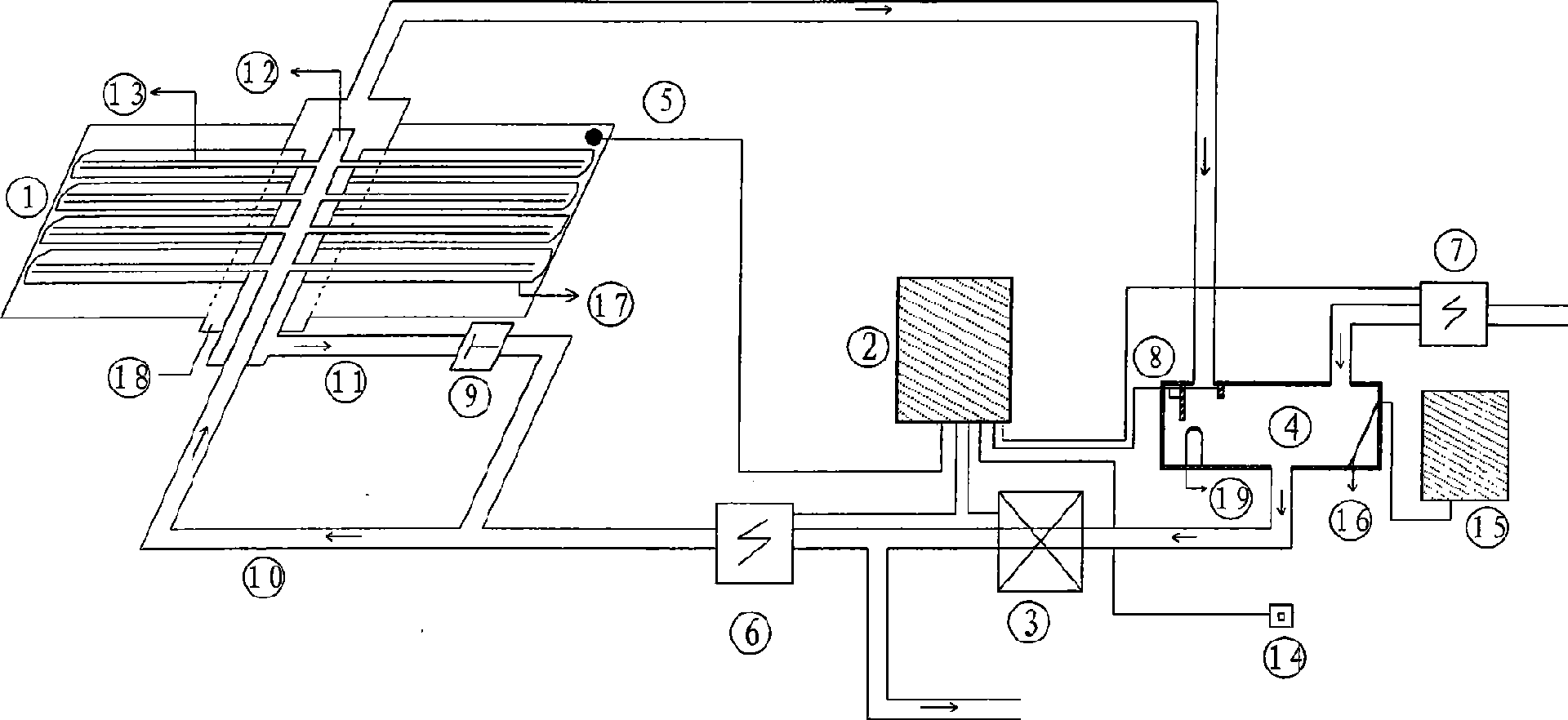
[0022] The light-controlled non-pressurized split solar water heater shown in the figure includes a solar collector 1 installed outdoors, a light-controlled integrator 2, a non-pressurized water tank 4 installed indoors, and a heat collector 1. It is composed of a plurality of vacuum glass tubes 17 arranged horizontally. The connection to the vacuum tubes 17 is connected by a concentrator 18. A main tube 12 is provided in the concentrator 18, and a branch tube is provided in each vacuum tube 17. 13. A cold water inlet and a solenoid valve 7 are provided above the water tank 4, a water level sensor 8 and a temperature water level sensor 16 are provided in the water tank 4, and the solar water heater passes through the water tank 4, the circulation pump 3, the solenoid valves 6, 7, and 12 female and 13 water guide pipes. , light sensor 5, light c...
PUM
 Abstract
Description
Claims
Application Information