Apparatus and method for monitoring metal corrosion under organic coating

A metal corrosion and organic coating technology, applied in the field of devices for monitoring metal corrosion under organic coatings, can solve the problems of environmental pollution, social impact, shedding, time-consuming and cost-consuming, etc., and achieves simple and flexible operation, small passivation current, low-cost effects

Inactive Publication Date: 2009-05-13
INST OF OCEANOLOGY - CHINESE ACAD OF SCI
View PDF0 Cites 14 Cited by
  • Summary
  • Abstract
  • Description
  • Claims
  • Application Information

AI Technical Summary

Problems solved by technology

Due to the harsh corrosive environment of the atmosphere, soil, seawater, and sea mud, the transportation pipeline is especially affected by the H caused by industrial production. 2 S, SO 2 , CO 2 And the corrosion of other substances, the surface protective coating will fail or be partially damaged after long-term use, resulting in the exposure of the pipeline substrate to the corrosive medium, resulting in serious corrosion of pipelines and other important production facilities
For example, natural gas produced in some gas fields in western Sichuan contains H 2 S, SO 2 There is less corrosive gas, and the internal corrosion of the pipeline is relatively light. However, because the gas pipeline is buried in the soil, it has been in a harsh corrosive environment for a long time, resulting in the failure, peeling and damage of the external coating of the pipeline, resulting in serious external corrosion of the pipeline.
Once the pipeline is corroded and causes oil and natural gas leakage, it

Method used


Image

  • Apparatus and method for monitoring metal corrosion under organic coating
  • Apparatus and method for monitoring metal corrosion under organic coating
  • Apparatus and method for monitoring metal corrosion under organic coating

Examples


Embodiment Construction

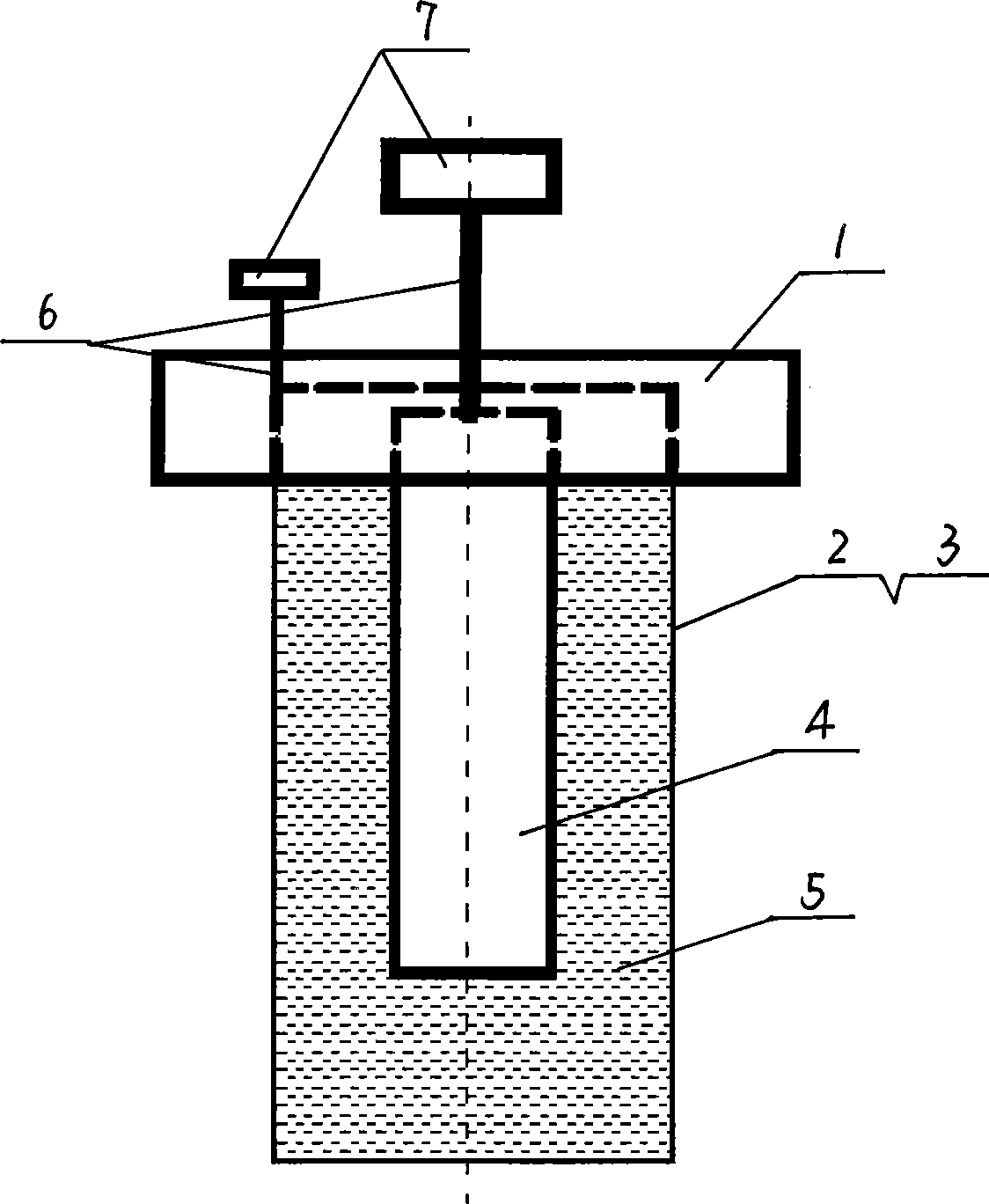
[0026] The present invention will be described in further detail below in conjunction with the accompanying drawings.

[0027] Such as figure 1 As shown, the present invention includes an electrolytic cell cap 1, a bucket 2 identical to the metal material to be monitored, a nickel rod 4 and a connector 7. The present embodiment adopts a 35CrMo steel thin-walled cylinder with a wall thickness of 0.3-0.5mm. The inner wall of the drum 2 is plated with a nickel layer, and the outer surface is provided with a coating 3. The coating of this embodiment is a commercially available product, and the EPONICS SHB (ultra-thick film epoxy coating Co., Ltd. Resin coating), electrolyte solution 5 is housed in drum 2. The lower end of the electrolytic cell cap 1 is provided with a groove, and one end of the nickel rod 4 is inserted into the electrolyte 5 in the drum 2, but not in contact with the inner wall of the drum 2, and the other end is connected with the electrolytic cell cap 1, and th...


PUM


Abstract

The invention relates to a device for monitoring metallic corrosion, in particular to a device for monitoring the metallic corrosion under an organic coat and a monitoring method thereof. The device comprises an electrolytic cell cap, a barrel made from the material same as metallic material to be monitored, a nickel bar and a socket connector. The nickel bar which is equipped with a shielded conductor is connected with the electrolytic cell cap. The internal wall of the barrel is plated with nickel, the external surface is coated with a coat uniformly, then electrolyte is put in the barrel, and the nickel bar is inserted in the barrel. The shielded conductor at the barrel and the nickel bar is led out by the electrolytic cell cap. The led-out shielded conductor is connected with a potentiostat by the socket connector. The inside of the barrel is provided with a corrosion signal monitoring working electrolytic cell. A nickel-plated surface on the internal wall of the barrel is a signal detection working face. The external wall of the barrel and a coat surface on the external wall are corrosion reaction faces. A signal output end of the potentiostat is connected with a data collector and a computer for collecting a monitoring device signal and realizing the monitoring towards the metallic corrosion degree and the corrosion speed under the coat. The invention can monitor the metallic corrosion status under the coat fast and continuously for a long time.

Description

technical field [0001] The invention relates to a monitoring device for metal corrosion, in particular to a device for monitoring metal corrosion under an organic coating and a monitoring method thereof. Background technique [0002] All major developed countries in the world attach great importance to the monitoring of metal material corrosion and environmental corrosion. In the 1980s, the British North Sea Oilfield actively carried out marine corrosion environment measurement, evaluated its corrosion capability and drew a corrosion map. Corrosion monitoring has been widely used on offshore oil platforms in various countries. [0003] With the continuous development of my country's oil and natural gas industry for decades, more and more oil and natural gas production facilities and pipelines have been extensively constructed. The external corrosion protection of these pipelines is generally undertaken by a protection system consisting of coating and cathodic protection. ...

Claims


Application Information

Patent Timeline
IPC IPC(8): G01N17/02G01N27/30
Inventor 于青黄彦良郑传波
Owner INST OF OCEANOLOGY - CHINESE ACAD OF SCI
Why Eureka
Try Eureka