Non-stress fixed installation structure of astronautic camera special-shaped glass prism

A special-shaped prism and installation structure technology, applied in the field of aerospace optical remote sensors

Inactive Publication Date: 2009-05-13
BEIJING RES INST OF SPATIAL MECHANICAL & ELECTRICAL TECH
View PDF0 Cites 10 Cited by
  • Summary
  • Abstract
  • Description
  • Claims
  • Application Information

AI Technical Summary

Problems solved by technology

[0005] At present, there are many cameras at home and abroad that use the prism system. How to overcome the defects o...

Method used


Image

  • Non-stress fixed installation structure of astronautic camera special-shaped glass prism
  • Non-stress fixed installation structure of astronautic camera special-shaped glass prism

Examples


Embodiment Construction

[0020] The present invention will be further described below in conjunction with accompanying drawing.

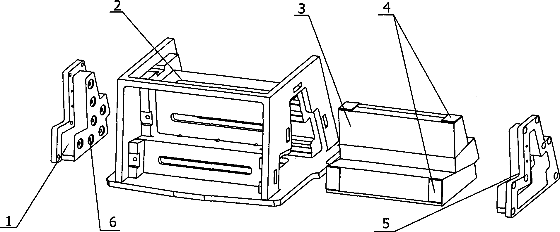
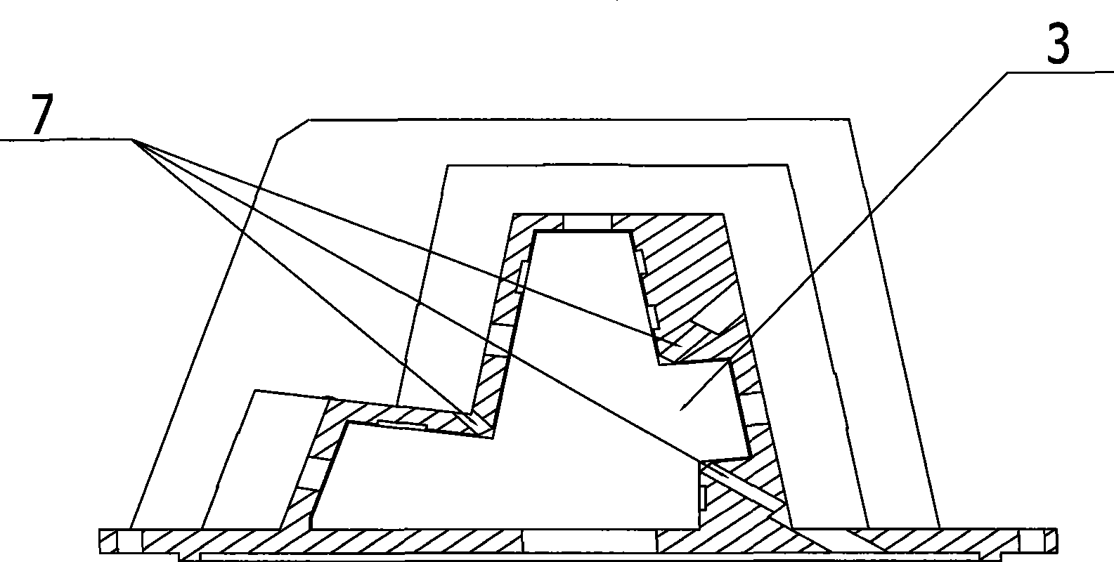
[0021] like figure 1 Shown, a kind of aerospace camera special-shaped prism stress-free fixed installation structure of the present invention comprises left block 1, special-shaped prism frame 2, special-shaped optical prism 3 and right stopper 5; Special-shaped optical prism 3 is installed in special-shaped prism frame 2 The left stopper 1 and the right stopper 5 respectively block the two sides of the special-shaped prism frame 2, and keep a certain gap with the special-shaped optical prism 3; 4; The left block 1 and the right block 5 are provided with step-shaped block glue injection holes 6 .

[0022] The special-shaped optical prism 3 in the present embodiment comprises three trapezoidal dichroic prisms that are glued together. On the bottom surface of the special-shaped prism frame 2, it is used as the incident surface of the prism light; the lower side of the secon...


PUM

PropertyMeasurementUnit
Thicknessaaaaaaaaaa
Diameteraaaaaaaaaa

Abstract

The invention discloses a non-strain fixing-mounting structure of an astronautic camera special-shaped prism, which comprises a left baffle (1), a special-shaped prism framework (2), a special-shaped optical prism (3) and a right baffle (5); the special-shaped optical prism (3) is mounted in the special-shaped prism framework (2); the left baffle (1) and the right baffle (5) are respectively blocked at the two sides of the special-shaped prism framework (2); strain-removing thermal treatment is carried out on the special-shaped prism framework (2), the left baffle (1) and the right baffle (5); the contact parts between the top part and the bottom part of the special-shaped optical prism (3) and the special-shaped prism framework (2) are provided with patches (4); the left baffle (1) and the right baffle (5) are provided with baffle glue injecting holes (6). As an integral opening structure is adopted by the invention, a refine linear cutting mode is adopted in processing; simultaneously strain-removing treatment is adopted to the framework structure, thus leading the strain of the special-shaped prism framework to the smallest while ensuring the processing precision, thereby avoiding the structure deformation to affect the optical performances of the prism.

Description

technical field [0001] The invention belongs to the technical field of aerospace optical remote sensors, in particular to a prism system used for mounting and fixing an aerospace optical camera. Background technique [0002] With the rapid development of aerospace optical camera technology, the resolution of optical remote sensors is getting higher and larger, and the demand for multispectral cameras is increasing, making optical prisms widely used in aerospace cameras. One aspect of the application is to meet the larger optical field of view of the camera. Since the size of the imaging device is limited in scale, a large number of devices are optically spliced ​​to meet the requirements of the camera for the optical field of view. On the other hand, it is applied to a multi-spectral camera, and a prism splitting system is used to meet the requirements of multi-spectral output. With the improvement of the performance index of the camera optical system, higher requirements ...

Claims


Application Information

Patent Timeline
IPC IPC(8): G02B7/18G03B17/02B64G1/66
Inventor 雷文平黄颖伏瑞敏郭悦张建国
Owner BEIJING RES INST OF SPATIAL MECHANICAL & ELECTRICAL TECH
Why Eureka
Try Eureka