

Method for making airtight container
A technology of an airtight container and a manufacturing method, which are applied in the manufacture of discharge tubes/lamps, manufacturing tools, and cold cathode manufacturing, etc., can solve the problem that bonding members cannot be uniformly attached to the substrate, and achieve the effect of improving airtightness
- Summary
- Abstract
- Description
- Claims
- Application Information
AI Technical Summary
Problems solved by technology
Method used
Image

Examples
Embodiment 1
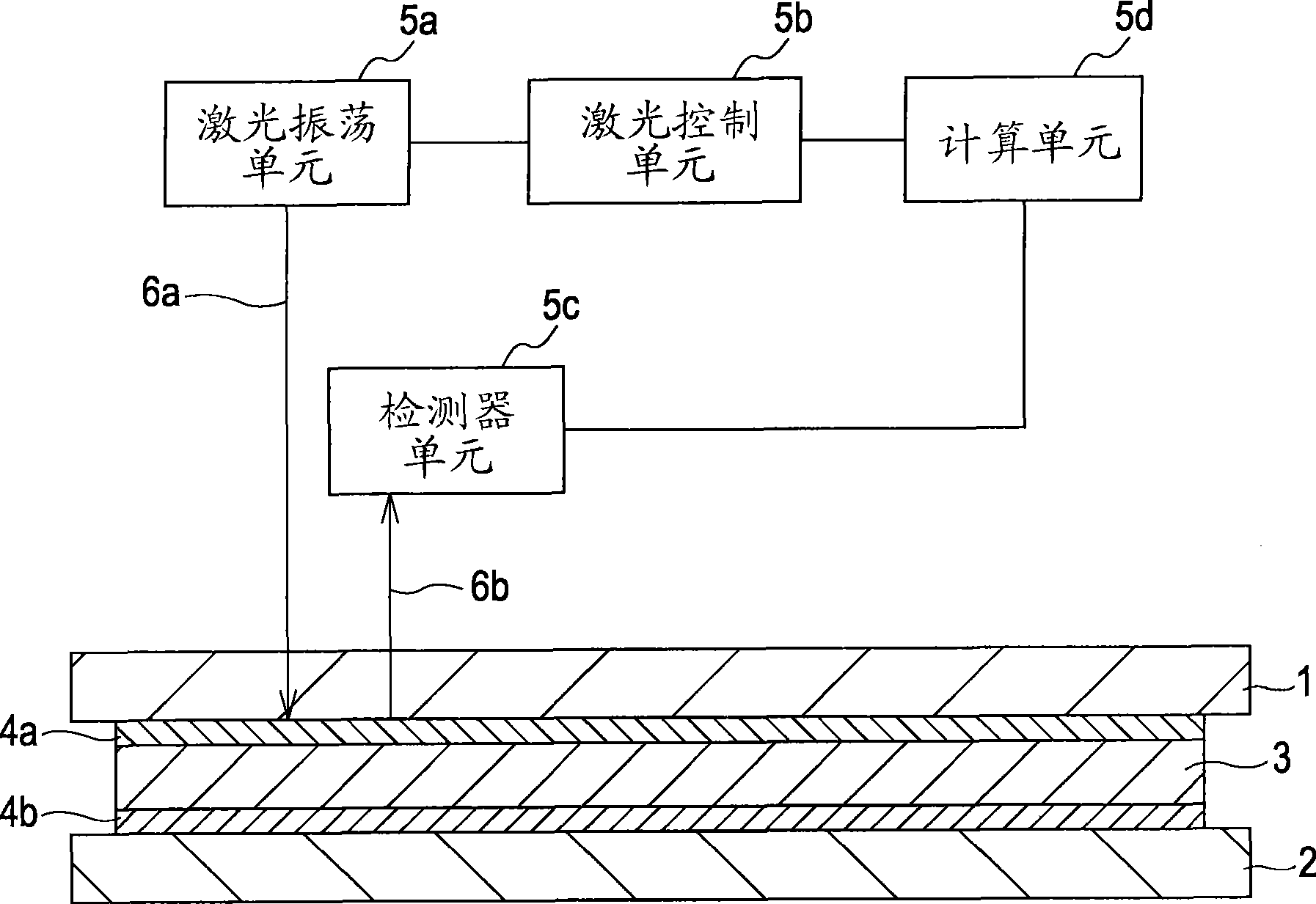
[0048] will now refer to figure 1 Example 1 of the present invention will be described. Embodiment 1 relates to a method in which the laser light used to melt the sealing member is also used to detect the melting state of the sealing member. According to the present embodiment, only one laser oscillation unit is required, so that the equipment (mechanism) can be simplified.
[0049] In Example 1, glass substrates (PD200 manufactured by Asahi Glass Co., Ltd.) having a size of 300 mm×350 mm and a thickness of 1.8 mm were used as the first substrate 1 and the second substrate 2 . A rectangular frame in plan view with a size of 280 mm×330 mm and a thickness of 1.8 mm prepared from a glass substrate was used as the supporting frame 3 .
[0050] First, the support frame 3 coated with the sealing member 4b is placed on the second substrate 2 and baked in an atmospheric furnace, thereby bonding the second substrate 2 to the support frame 3 with the sealing member 4b. In this embod...
Embodiment 2
[0060] Figure 4 The structure of an apparatus for implementing the method according to Embodiment 2 of the present invention is shown. The same constituent elements as those of the apparatus of Embodiment 1 are denoted by the same reference numerals.
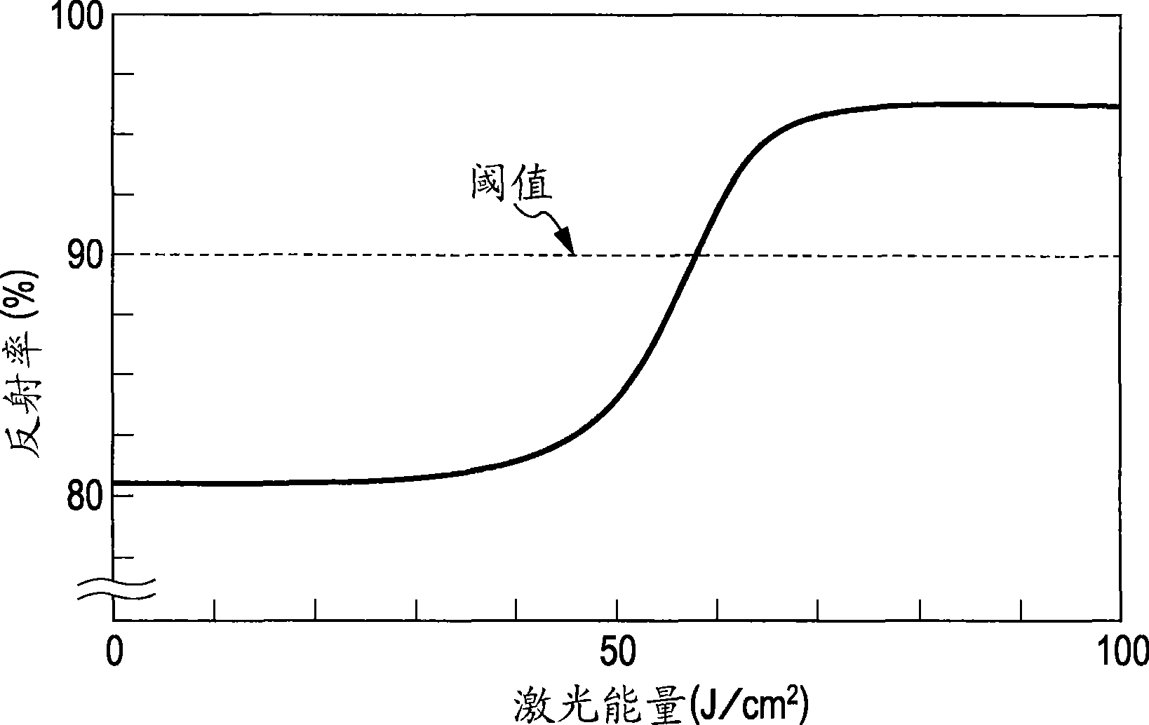
[0061] In Embodiment 1 described above, the change in reflectance is detected using the reflected light 6b of the laser beam 6a used to melt the sealing member 4a. In contrast, in Embodiment 2, the light source unit 41 for emitting the laser beam 42a which is a reference beam for detecting a change in reflectance is provided separately from the laser oscillation unit 5a. In other words, a plurality of laser oscillation units are used so that the laser beam used to melt the joined member is different from the laser beam used to detect the melting state.
[0062] In particular, the laser beam 42a (second laser beam) emitted from the light source unit 41 irradiates the portion of the sealing member 4a melted by the laser beam 6a...
Embodiment 3
[0068] Figure 5 The structure of an apparatus for implementing the method according to Embodiment 3 of the present invention is shown. The same constituent elements as those of the apparatus of Embodiment 1 are denoted by the same reference numerals.
[0069] In Embodiment 1 described above, the change in reflectance is detected using the reflected light 6b of the laser beam 6a used to melt the sealing member 4a. In contrast, in Embodiment 3, the reference beam 52a for detecting a change in reflectance is formed by dividing the laser beam 6a with the partial reflection mirror 51a. In other words, the laser beam emitted from the laser oscillation unit 5a is divided into a laser beam for melting the joined member and a laser beam for detecting the melting state by the split mechanism. According to this structure, the power of the laser beam suitable for melting the bonded member and the power of the laser beam (light source) suitable for measuring the reflectance can be selec...
PUM
| Property | Measurement | Unit |
|---|---|---|
| thickness | aaaaa | aaaaa |
| wavelength | aaaaa | aaaaa |
Abstract
Description
Claims
Application Information