Thermal storage cremation furnace for storing press and cleaning

An incinerator and heat storage technology, applied in incinerators, lighting and heating equipment, combustion methods, etc., can solve problems such as pollution in practical places, pollution switching peaks, and industry troubles

Inactive Publication Date: 2009-05-20
DESICCANT TECH CORP
View PDF0 Cites 14 Cited by
  • Summary
  • Abstract
  • Description
  • Claims
  • Application Information

AI Technical Summary

Problems solved by technology

In the commonly used regenerative incinerator 10a, when the inlet and outlet valves of the double-tower incinerator are used to switch the regenerative bed during the operation cycle, a peak emission equivalent to the inlet concentration will be generated to the chimney (discharge port). The destruction efficiency can reach more than 98%, and the inlet airflow will be directly discharged to the chimney when switching. Based on the 98% destruction efficiency estimate, it can be seen that this concentration is 50 times higher than that of the exhaust gas passing through the incinerator, which has always caused industrial pollution. Moreover, after the switching is completed, the heat storage bed originally used for intake air preheating will become the heat storage bed for exhaust heat storage. At this time, the exhaust gas that originally existed in the heat storage bed will not Entering the combustion chamber for incineration and decomposition treatment, it is still untreated waste gas, which will be blown out by the air flow due to the reverse flow of the air flow, and become pollution
It is known that the disadvantage of commonly used regenerative incinerators is that when the airflow direction of the valve is switched, a switching peak of pollution will be generated, and the lack of pollution makes it have its shortcomings in practical applications.

Method used


Image

  • Thermal storage cremation furnace for storing press and cleaning
  • Thermal storage cremation furnace for storing press and cleaning
  • Thermal storage cremation furnace for storing press and cleaning

Examples


Embodiment Construction

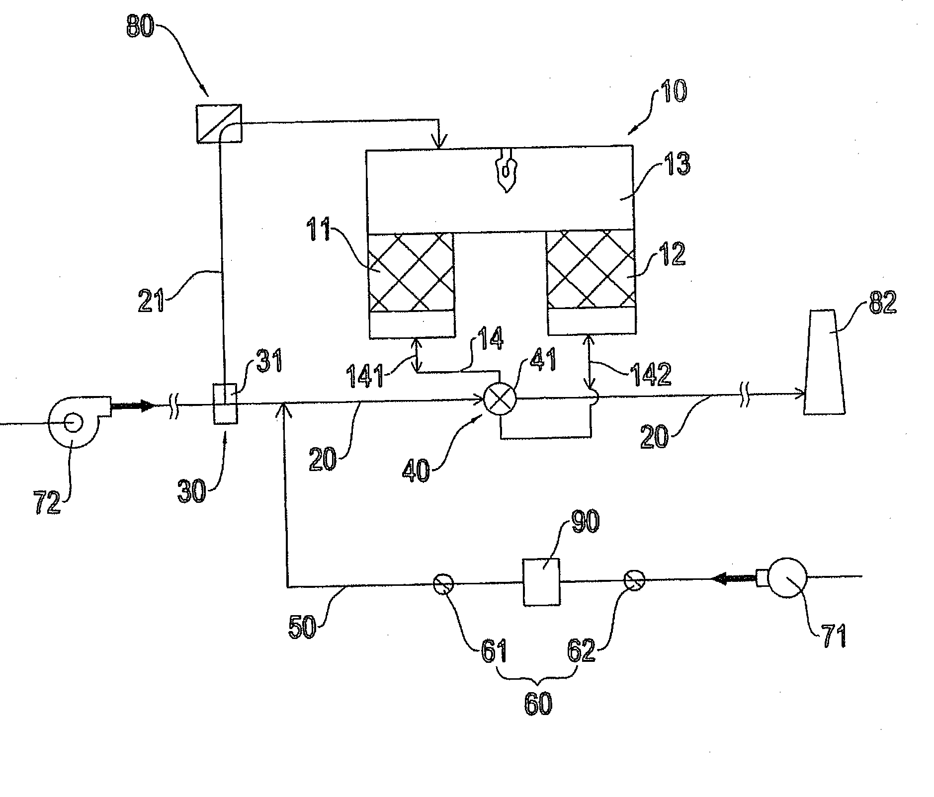
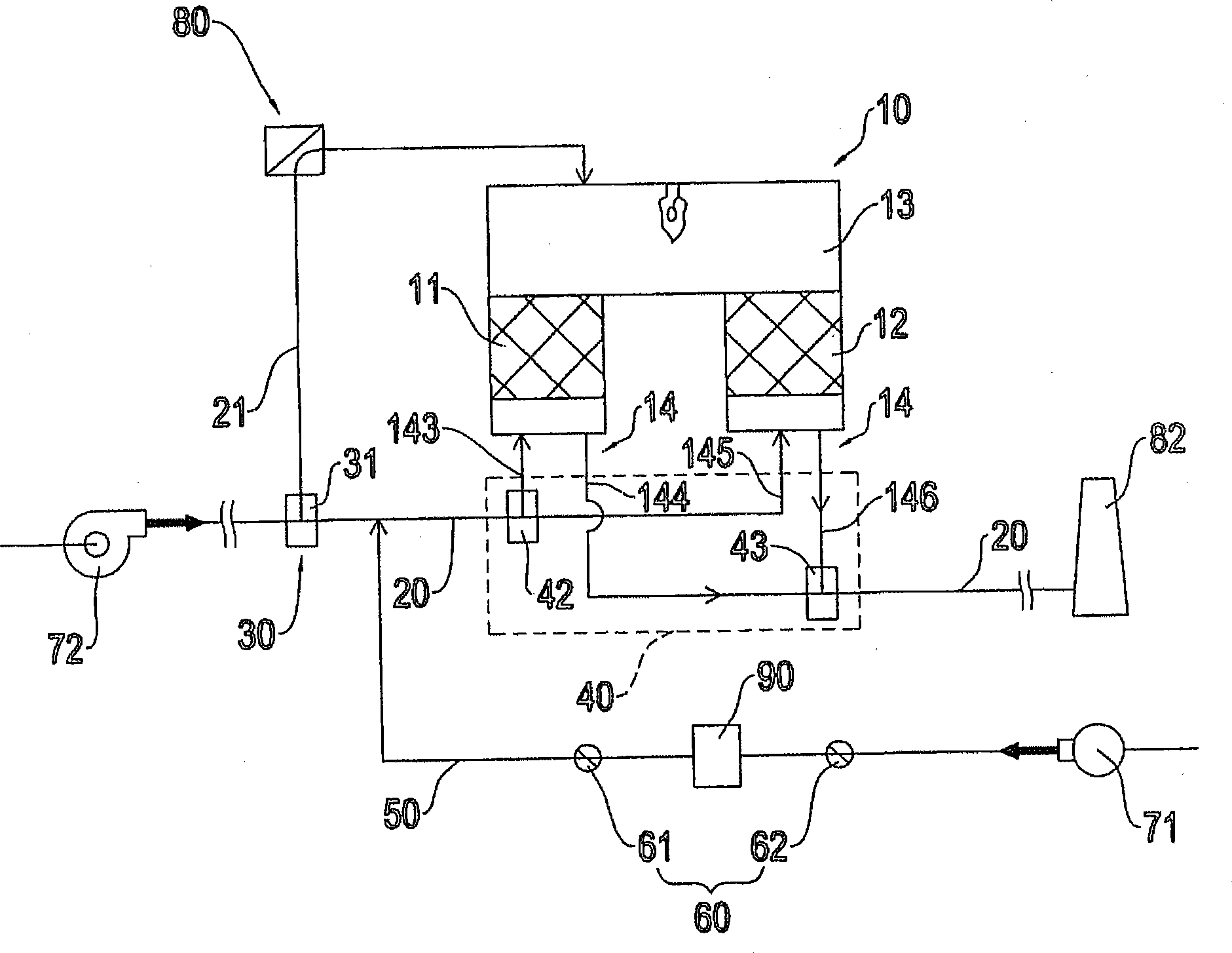
[0062] Please refer to figure 2 As shown, it is a schematic structural view of the heat storage incinerator for pressure storage and purification of the present invention, which includes a heat storage incinerator 10, a waste gas main pipeline 20, a waste gas inlet valve group 30, a leading control valve group 40, a Clean gas air supply pipeline 50, a pressure storage tank 90, a gas control valve group 60 and a compressed gas equipment 71; the heat storage incinerator 10 is provided with a first heat storage bed 11, a second heat storage bed 12 and A combustion chamber 13, the combustion chamber 13 is a space communicating with the tops of the first heat storage bed 11 and the second heat storage bed 12, and the first heat storage bed 11 and the second heat storage bed 12 are respectively equipped with at least A ventilation pipeline 14 (the first ventilation pipeline 141, the second ventilation pipeline 142) is used for the entry and exit of gas, wherein the first heat stora...


PUM


Abstract

The invention relates to a heat accumulating incinerator for accumulating pressure and cleaning. A main waste gas pipeline is connected with a ventilating pipeline of the heat accumulating incinerator, a waste gas bypass pipeline is provided with a waste gas inlet valve group and a flow direction control valve group for controlling a switching pipeline and controlling flow direction of waste gas in the pipeline, one end of a clean gas blast pipeline is connected with the main waste gas pipeline to feed gas into the main waste gas pipeline, the clean gas blast pipeline is provided with a pressure storage cylinder and a gas control valve group for supplying compressed air equipment, and gas generated by the pressure storage cylinder quickly enters the main waste gas pipeline at high pressure; and when the heat accumulating incinerator switches gas flow direction, the gas in the clean gas blast pipeline quickly flows to a ventilating pipeline of the heat accumulating incinerator through the main waste gas pipeline to remove leaked pollution generated when the gas flow direction is switched and make unburnt and untreated organic waste gas in a heat accumulating bed in the heat accumulating incinerator enter a combustion chamber of the incinerator to be treated, thereby preventing the untreated organic waste gas from being directly discharged, and removing pollution of the waste gas.

Description

technical field [0001] The present invention relates to a thermal storage incinerator for pressure storage and purification, and relates to a thermal storage incinerator (Regenerative Thermal Oxidizer, RTO). One leading to the control valve group, one clean air supply pipeline, one pressure storage barrel, one gas control valve group and one supply of compressed gas equipment, which can switch the flow direction of the regenerative combustion furnace while switching the regenerative bed The leakage pollution in the direction of the airflow is removed, and the other function is that the unburned waste gas of the heat storage bed will not leak out, and the untreated organic waste gas in the heat storage bed is pushed into the combustion chamber for treatment, so as to prevent the untreated organic waste gas from being damaged when switching. Discharge after switching to avoid the pollution peak of operation and achieve the function of stable utilization. It is suitable for indus...

Claims


Application Information

Patent Timeline
Patent Type & Authority Applications(China)
IPC IPC(8): F23G7/06
Inventor 郑石治扶亚民田磊徐瑞珠刘邦昱洪守铭
Owner DESICCANT TECH CORP
Why Eureka
Try Eureka