On-line checking method of quality and flow controller
A technology of mass flow and calibration method, applied in the field of microelectronics, can solve the problems of reduced use efficiency and long time consumption of plasma processing equipment, and achieve the effect of shortening detection time and improving use efficiency
- Summary
- Abstract
- Description
- Claims
- Application Information
AI Technical Summary
Problems solved by technology
Method used
Image

Examples
Embodiment Construction
[0036] The core of the present invention is to provide an on-line verification method of a mass flow controller, which consumes less time in the verification process.
[0037] In order to enable those skilled in the art to better understand the solution of the present invention, the present invention will be further described in detail below in conjunction with the accompanying drawings and specific embodiments.
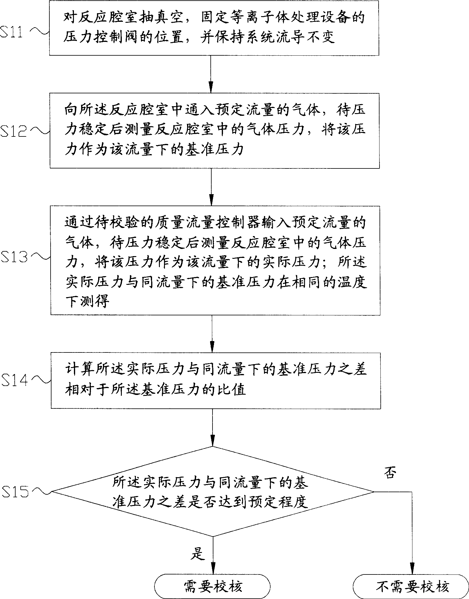
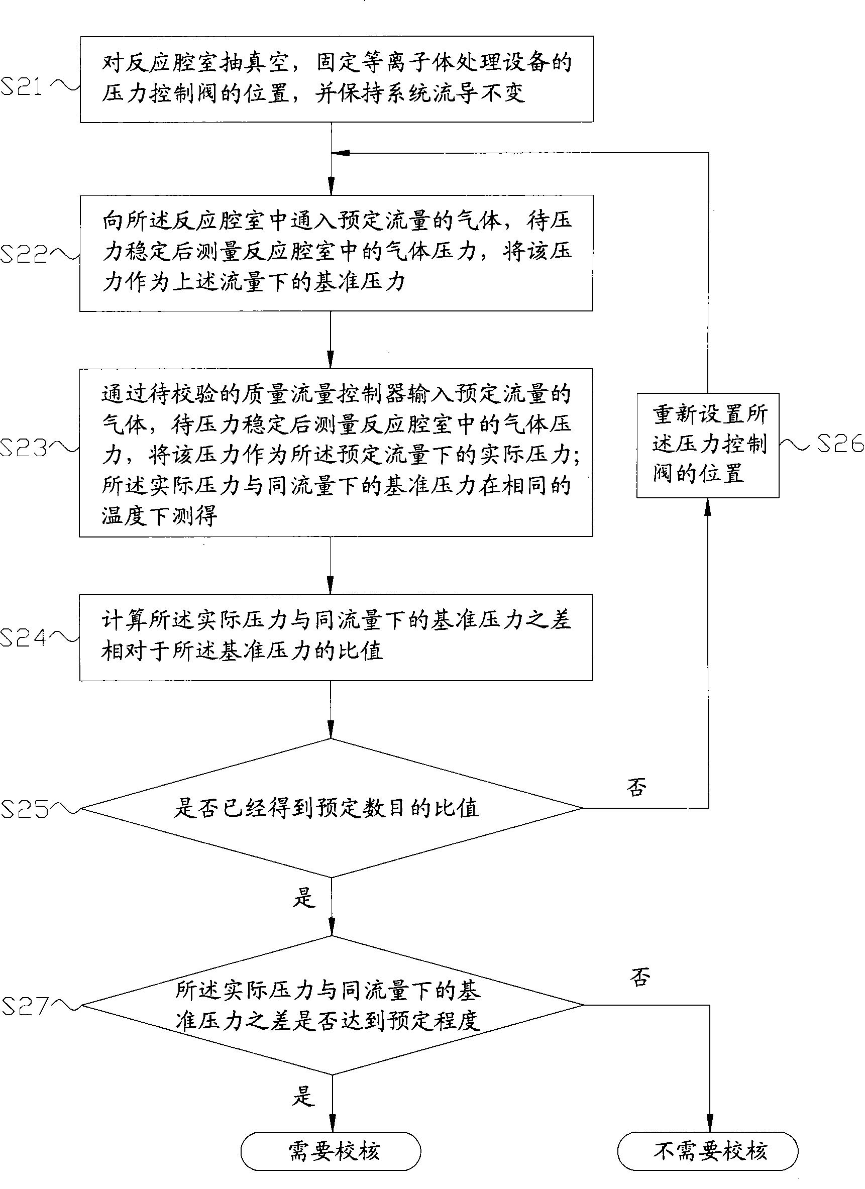
[0038] Please refer to figure 2 , figure 2 It is a flow chart of the online verification method of the mass flow controller provided by the first specific embodiment of the present invention.
[0039] In the first specific implementation mode, the online calibration method of the mass flow controller provided by the present invention includes the following steps:
[0040] Step S11:
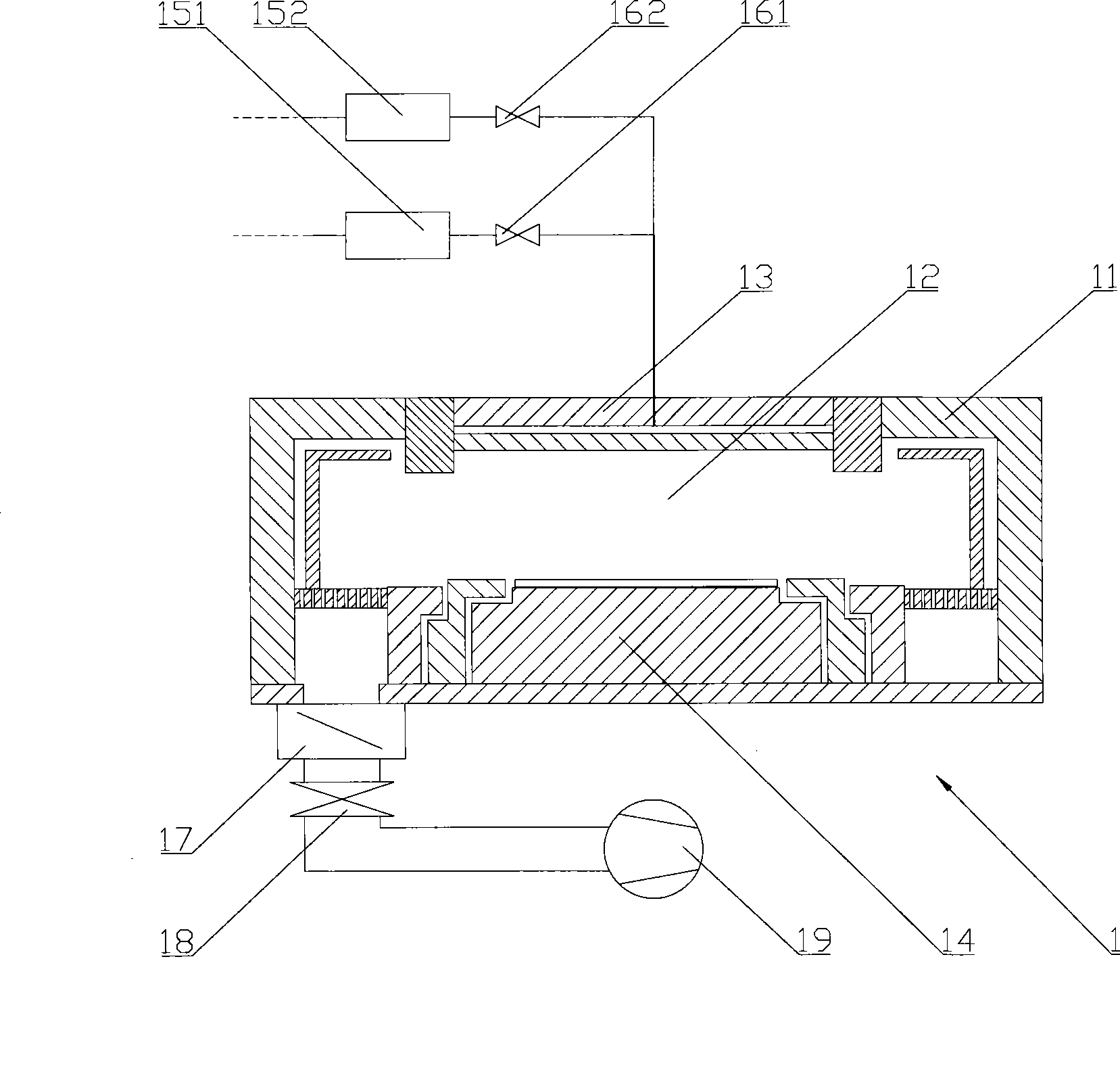
[0041] Vacuumize the reaction chamber 12 through a vacuum pump group 19 or other vacuum obtaining devices, and keep the pumping speed constant; at the same time, fix the position of t...
PUM
 Abstract
Description
Claims
Application Information