
Preparation method for metal key-press with corrugated brightness

A key and metal technology, applied in the field of metal key production, can solve the problems such as the transparent plastic film 2a and the transparent elastic layer 5a cannot be fully squeezed, the internal circuit is short-circuited, and the appearance of the metal key 10a is dull and visually dull.

Inactive Publication Date: 2009-05-20
ICHIA TECH
View PDF1 Cites 5 Cited by
  • Summary
  • Abstract
  • Description
  • Claims
  • Application Information

AI Technical Summary

Problems solved by technology

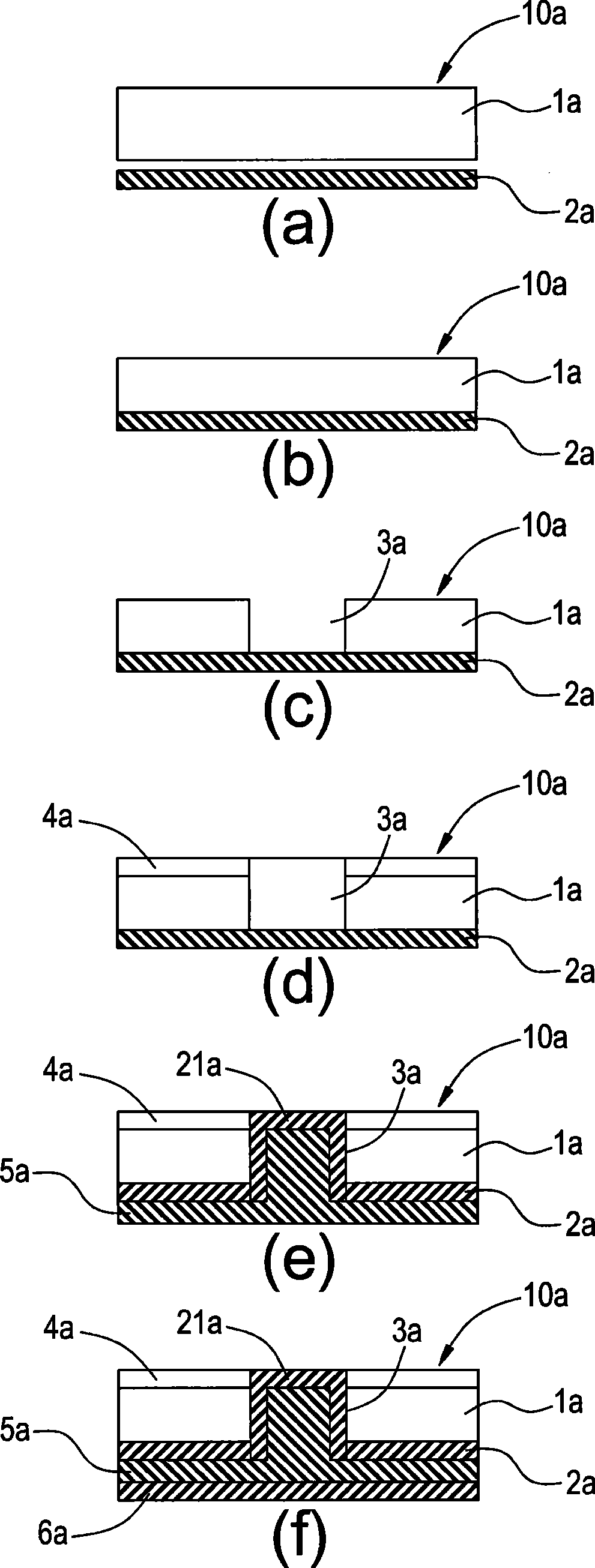
[0004] When making the above-mentioned metal key 10a, since the transparent plastic film 2a and the transparent elastic layer 5a are extruded together in the hollow part 3a, the extrusion force and heating temperature in the hot extrusion process must be properly controlled, otherwise the transparent plastic will be damaged. The film 2a and the transparent elastic layer 5a cannot be completely squeezed into the hollow part 3a, resulting in defective products
Even, in the process of extruding the transparent plastic film 2a and the transparent elastic layer 5a on the hollow part 3a, it is easy to cause the friction and pulling state between the transparent plastic film 2a and the wall and chamfer of the hollow part 3a, and it is easy to cause the transparent plastic film 2a to break , thus causing difficulties in making
[0005] Secondly, a gap is likely to be formed between the transparent plastic film 2a squeezed in the hollow portion 3a and the wall surface of the hollow portion 3a, and the gap is easy to accumulate dust and liquid to infiltrate, resulting in unsmooth pressing of the metal key portion or short circuit of the internal circuit And other issues
[0006] In addition, the surface of the transparent resin layer 4a formed on the metal plate 1a is flat, which only provides the protection of the metal plate 1a without any special glossy reflection effect, making the overall appearance of the metal key 10a too dull.

Method used


Image

  • Preparation method for metal key-press with corrugated brightness
  • Preparation method for metal key-press with corrugated brightness
  • Preparation method for metal key-press with corrugated brightness

Examples


Embodiment Construction

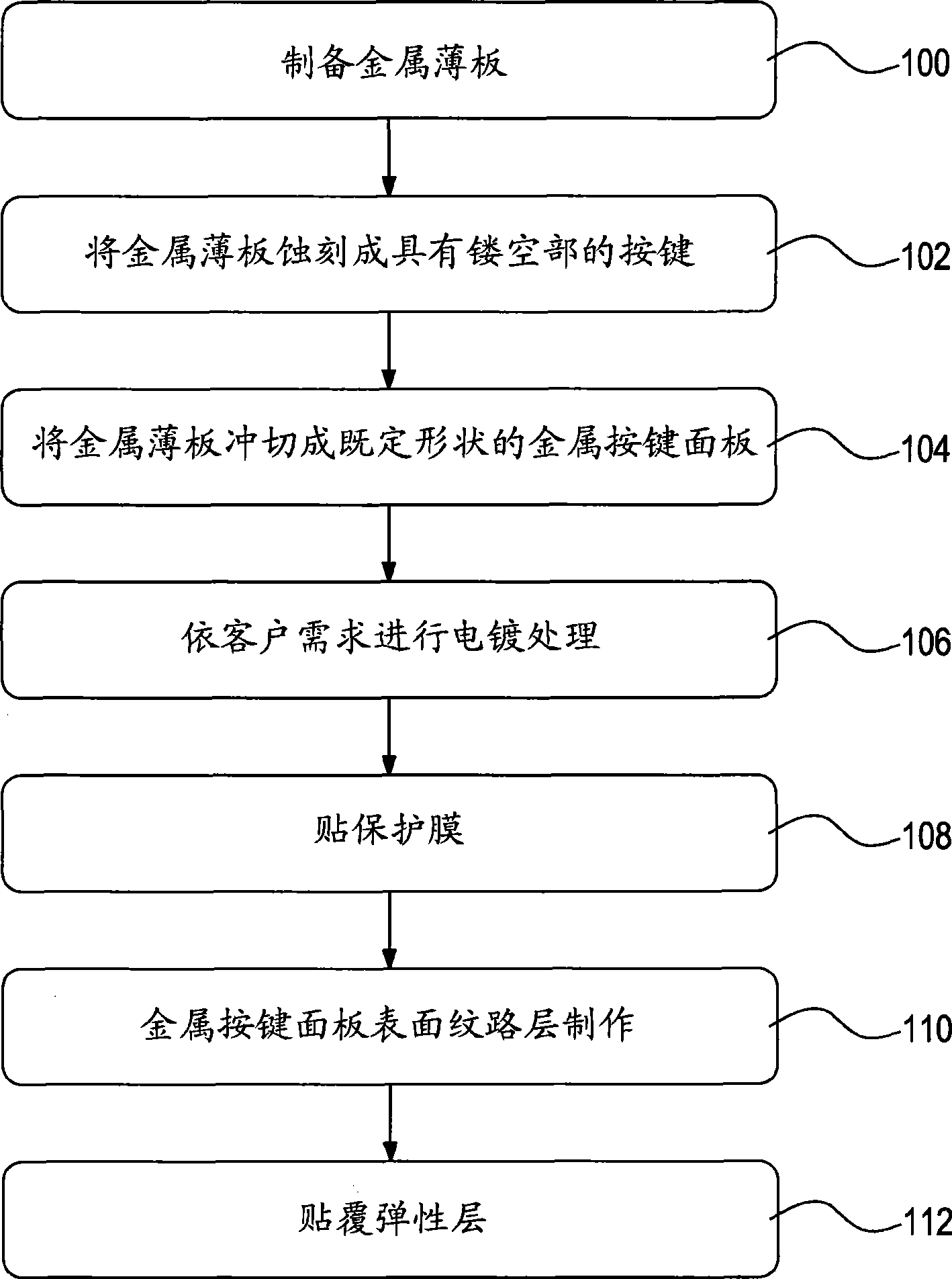
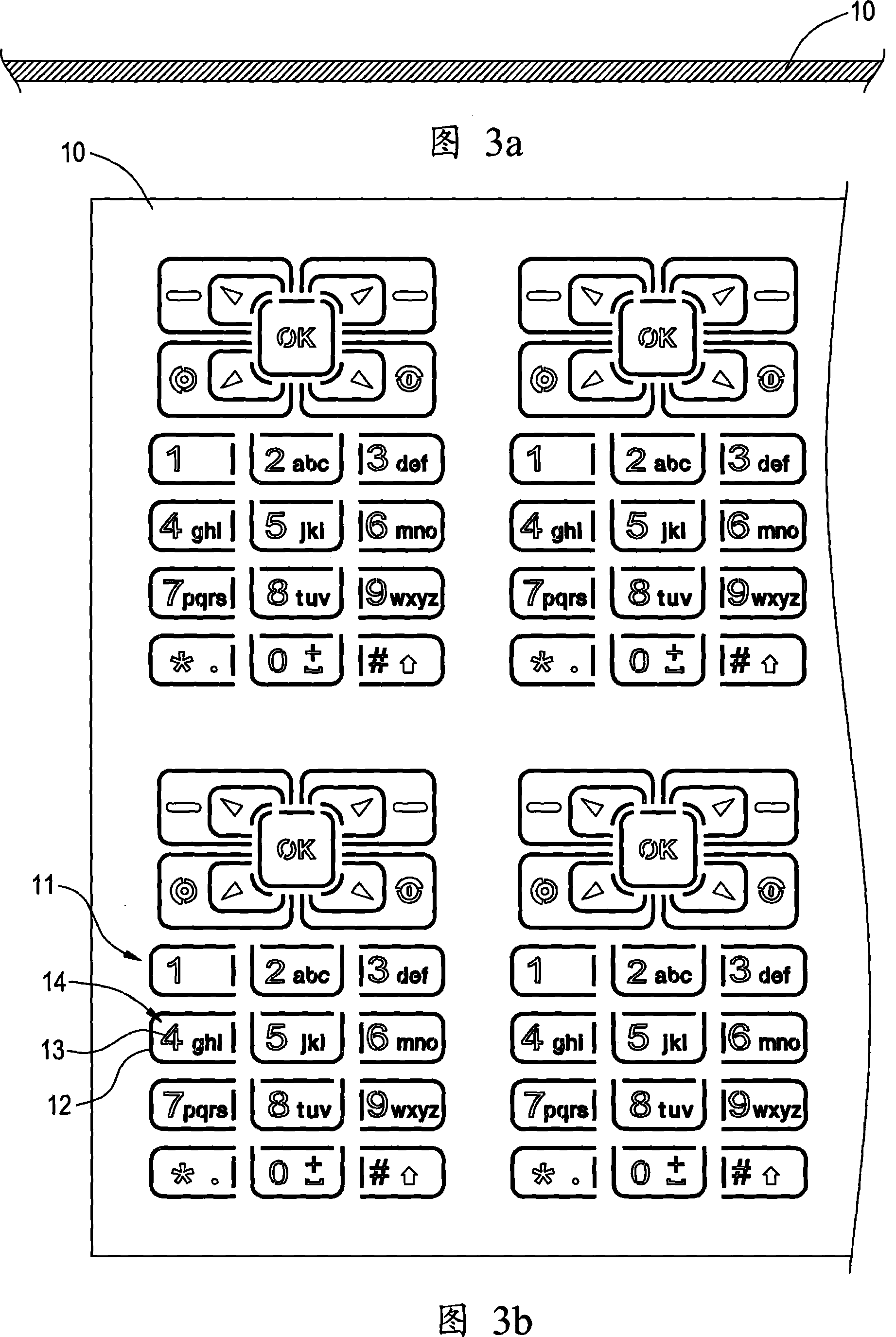
[0045] The technical content of the present invention is described in detail below in conjunction with accompanying drawing: figure 2 It is a schematic diagram of the metal button production process of the present invention. As shown in the figure: please refer to Fig. 3 for the manufacturing method of the metal button with corrugated luster of the present invention. First, as in step 100, a thin metal plate 10 is prepared, as shown in Fig. 3(a), the thin metal plate 10 is stainless steel (SUS) or aluminum-magnesium alloy materials.

[0046] In step 102 , etching is performed on the thin metal plate 10 to form a plurality of hollow parts 11 on the thin metal plate 10 . The hollow parts 11 are divided into line hollow parts 12 and pattern hollow parts 13 . The pressing area 14 of the key is defined by the line hollow part 12, and the graphic hollow part 13 is set as a graphic on the surface of the pressing area 14, which includes numbers (0-9), characters (A-Z), special symbo...


PUM


Abstract

The invention provides a method for manufacturing a metal press key with rippling luster. The method comprises the following steps: firstly a metal sheet is prepared, by etching treatment, a plurality of hollow parts are formed on the metal sheet, the hollow parts are defined as a press zone of press keys and figures on the surface of the press zone, and the metal sheet is die-cut into the metal press keys with established shapes; secondly, the surfaces of the metal press keys are electroplated with an electroplated coating, and the surfaces of the metal press keys which are not electroplated are bonded with a layer of protective film; thirdly, the metal press keys are placed into a die, and the die is injected with a plastic material, so that the plastic material forms a rippling layer; and finally, the surfaces of the metal press keys which are not electroplated are covered with an adhesive layer, and an elastic layer with a plurality of protruding parts is covered on the surface of the adhesive layer, therefore the manufacture of the metal press key with rippling luster is completed.

Description

technical field [0001] The invention relates to a button, in particular to a method for manufacturing a metal button. Background technique [0002] The button panel has become an indispensable hardware structure of the electronic device. Moreover, numbers, characters, phonetic symbols, radicals of input methods and various functional graphics are arranged on the surface of the keys of the key panel, so that the user can input data or execute various functions of the electronic device. Therefore, the button panel is not only indispensable for the handheld electronic device, but also an extremely important input device. [0003] Metal buttons on traditional electronic devices, such as figure 1 (a) to (f) (Japanese Laid-Open Patent Publication No. 2007-134071). in production figure 1 When the metal button 10a is used, a metal plate 1a is first prepared, and the metal plate 1a is pasted on the transparent plastic film 2a, and then the metal plate 1a is formed into a hollow p...

Claims


Application Information

Patent Timeline
IPC IPC(8): H01H11/00H01H13/14H01H13/70
Inventor 吴哲东许志和曹凯杰
Owner ICHIA TECH
Learn More