Supercharge Your Innovation With Domain-Expert AI Agents!

LED chip component with heat-dissipating substrate and preparation method thereof

A technology of light-emitting diodes and heat-dissipating substrates, which is applied in semiconductor/solid-state device manufacturing, electrical components, electric solid-state devices, etc., can solve the problems of destroying the heat conduction interface, affecting the heat dissipation efficiency of the component 1, and reducing the thermal resistance. Heat dissipation issues, the effect of improving light performance and working life

Inactive Publication Date: 2010-11-03
LIUNG FENG INDAL +1
View PDF11 Cites 1 Cited by
  • Summary
  • Abstract
  • Description
  • Claims
  • Application Information

AI Technical Summary

Problems solved by technology

[0006] However, in the structure of these existing light-emitting components 1, the bonding material 13 is used to bond the light-emitting diode chips 12. Therefore, the heat conduction is limited by factors such as the contact interface between the layers and the different thermal conductivity of each layer. It directly affects the luminous performance and working life of the light-emitting component 1; at the same time, based on the manufacturing method developed based on such a structure, the bonding material 13 is very easy to be stacked and crowded during the operation process of bonding the LED chip 12. Voids are formed by pressing, which destroys the heat conduction interface, greatly affects the heat dissipation effect of the component 1, and leads to the premature end of the working life of the component 1
[0007] Moreover, the international patent application with the application number WO2006112356A1 and the Japanese patent application with the application number JP2006339542A disclose a method for solving the heat dissipation problem by directly bonding the bare chip on the heat dissipation circuit board, and using the chip to achieve effective heat dissipation. The medium must be a material with good heat dissipation, and the heat dissipation area of ​​the component is still the contact area of ​​the grain size, which has a very limited impact on the actual thermal resistance reduction

Method used


Image

  • LED chip component with heat-dissipating substrate and preparation method thereof
  • LED chip component with heat-dissipating substrate and preparation method thereof
  • LED chip component with heat-dissipating substrate and preparation method thereof

Examples


Embodiment Construction

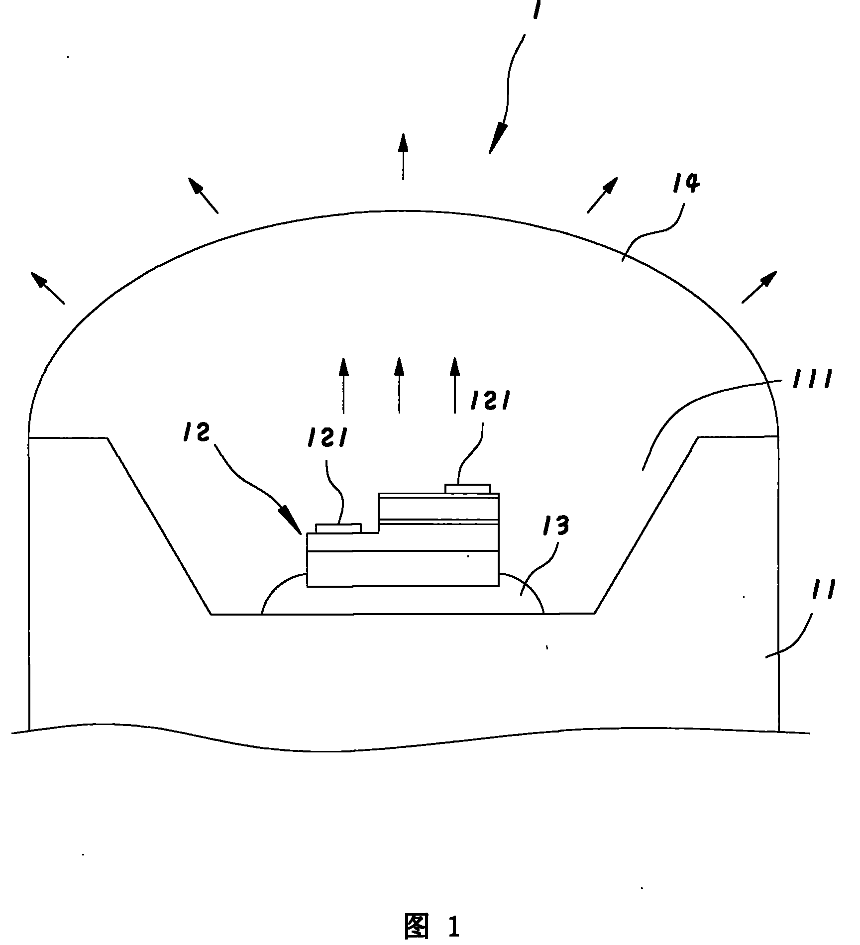
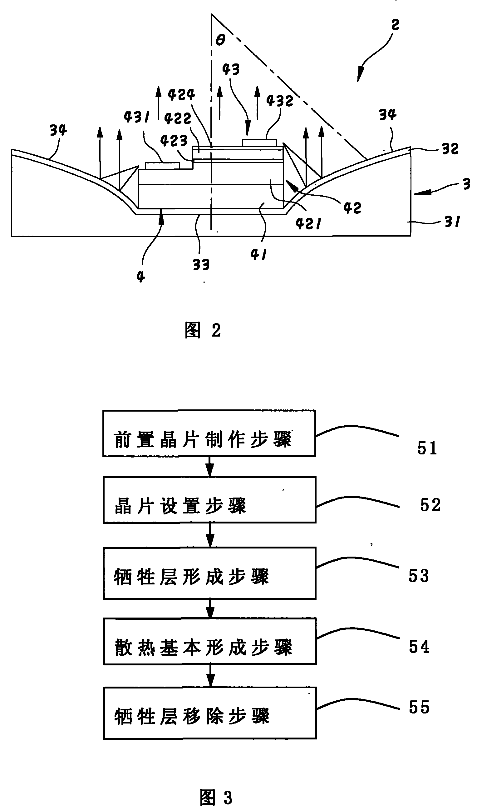
[0028] refer to figure 2 , which is a first preferred embodiment of the light-emitting diode chip assembly 2 with a heat-dissipating substrate in the present invention, including a heat-dissipating substrate 3, and at least one light-emitting diode chip 4 disposed on the heat-dissipating substrate 3, in this example, Only one light emitting diode chip 4 is provided, and the light emitting diode chip 4 is a general horizontal conducting light emitting diode chip.

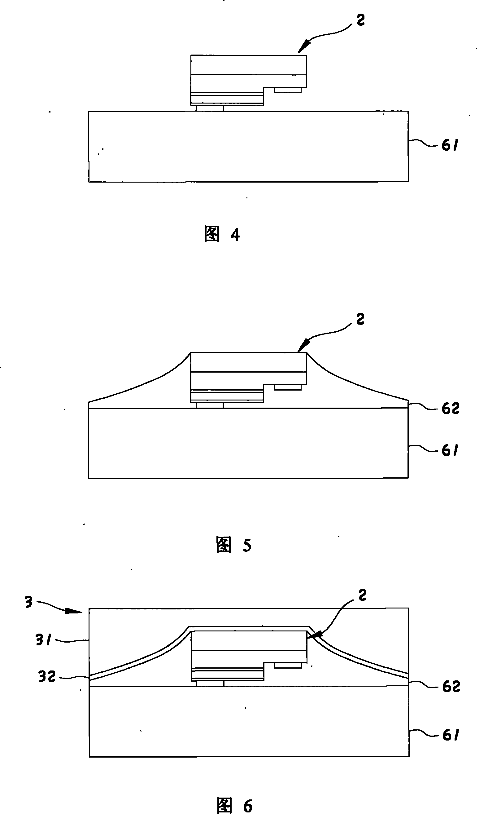
[0029] The heat dissipation substrate 3 is made of a material with high thermal conductivity, and can be formed by using a single material such as copper, gold, silver, nickel, tin, titanium, platinum, palladium, tungsten, molybdenum, or a combination of these materials. Substrate 31, and a mirror 32 formed on the substrate 31 to reflect light with a material having a high reflectance at the same time; in terms of its structure, it has a central portion 33, and a reflective portion 34 surrounding the central portion...


PUM


Abstract

The invention provides a light-emitting diode chip module provided with a heat radiating substrate and a method for manufacturing the same. The light-emitting diode chip module comprises a light-emitting diode chip and the heat radiating substrate which is made from a material with high thermal conductivity coefficient and is integrally connected with the light-emitting diode chip, wherein the heat radiating substrate is provided with a base material to contact the light-emitting diode chip directly, a central part which can conduct the heat away from the light-emitting diode chip directly, and a reflecting part which surrounds the central part and can reflect light emitted by the light-emitting diode chip so that the light is emitted upwards in a forward direction can radiate the heat ofthe module at high speed to prolong service life and improve the light emission of the module, wherein the normal line of the top surface of the reflecting part and the normal line of the top surfaceof the central part form an acute angle.

Description

technical field [0001] The present invention relates to a light emitting component and a manufacturing method thereof, in particular to a light emitting component including a light emitting diode chip (LED Chip) and a manufacturing method thereof. Background technique [0002] refer to figure 1 , the existing light-emitting component 1 with light-emitting diode chips 12 generally includes a base plate 11 that can conduct heat and has a concave hole 111, a light-emitting diode chip 12 that generates light by the photoelectric effect and is arranged in the concave hole 111, and is located in the concave hole 111. Between the bottom surface of the hole 111 and the LED chip 12 , a bonding material 13 for adhering the LED chip 12 , and a filler 14 filled transparently in the concave hole 111 to isolate the LED chip 12 from the outside world. [0003] The light-emitting diode chip 12 generally provides electric energy through the electrical connection wire (not shown) designed to...

Claims


Application Information

Patent Timeline
Patent Type & Authority Patents(China)
IPC IPC(8): H01L33/00H01L25/00H01L25/075H01L23/367H01L21/50H01L33/64
CPCH01L2224/32
Inventor 洪瑞华武东星蒋承忠萧翔允许苍林林恒毅
Owner LIUNG FENG INDAL
Features
  • R&D
  • Intellectual Property
  • Life Sciences
  • Materials
  • Tech Scout
  • Unparalleled Data Quality
  • Higher Quality Content
  • 60% Fewer Hallucinations
Learn More