Joining method

A joint method and a technology of joint parts, which are applied in the field of joints, can solve problems such as weakening of strength, and achieve the effect of suppressing the reduction of strength

Inactive Publication Date: 2009-05-20
OSAKA UNIV +1
View PDF2 Cites 21 Cited by
  • Summary
  • Abstract
  • Description
  • Claims
  • Application Information

AI Technical Summary

Problems solved by technology

[0011] The inventors of the present invention have found that during friction stir welding, components contained in the atmosphere, such as moisture, are involved in the molten metal by stirring parts such as probes, and that the stirring parts form the root surface of the weld seam and the contact surface of the shoulder. Oxide film is involved, hydrates and oxides are generated, and the strength is weakened.

Method used


Image

  • Joining method
  • Joining method
  • Joining method

Examples


Embodiment 1

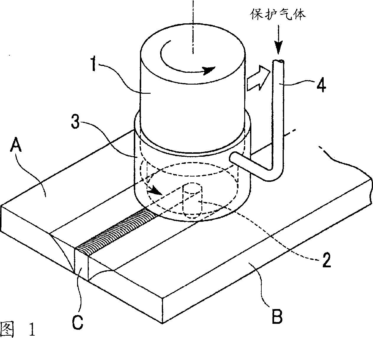
[0036] FIG. 1 shows an example of an apparatus used for friction stir welding of the present invention.

[0037] The device of this example generally includes: a cylindrical rotator 1 called a tool, a small-diameter cylindrical probe 2 protruding from the center of the bottom surface of the rotator 1, a cover 3 covering the lower part of the rotator 1, and a A shielding gas pipe 4 for supplying shielding gas is supplied to the space in the cover 3 .

[0038] An unillustrated pressing and rotating drive unit is provided on the top of the rotor 1 to rotate the rotor 1 while pressing the entire rotor 1 downward.

[0039] Symbols A and B in the figure represent plate-shaped members to be joined, and these members A and B to be joined are fixed in a state where their end faces are in close contact with each other, and the bonded portion becomes a joint between the end faces.

[0040] The probe 2 is rotated and pressurized to agitate the joint surface of the joint part by friction,...

Embodiment 2

[0053] In the friction stir welding of the present embodiment, the joint portion C is formed in a state of being in contact with air without flowing an inert shielding gas. As an apparatus for friction stir welding, the apparatus shown in FIG. 1 can be used as it is without supplying the shielding gas from the shielding gas pipe 4 .

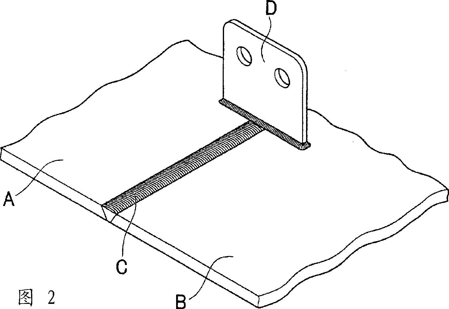
[0054] In the welding of other to-be-joined members D in the next step, fusion welding such as gas shielded welding such as TIG welding and MIG welding, electron beam welding, and laser welding is performed while applying or irradiating ultrasonic waves to the welded portion. The manner of this fusion welding is the same as that of Embodiment 1 shown in FIG. 2 previously.

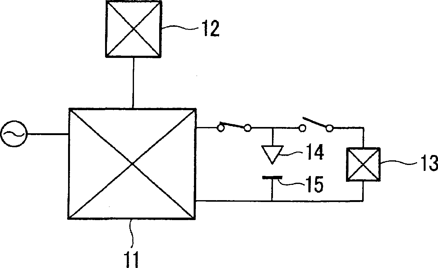
[0055] image 3 An example of a welding device for performing TIG welding while applying or irradiating ultrasonic waves to a welded portion is shown. This welding device includes: an AC power supply unit 11, a waveform control unit 12 for performing pulse width modulation (P...

Embodiment 3

[0064] Example 3 After forming the joining portion C by performing friction stir welding while flowing a shielding gas in the above-mentioned Example 1, performing fusion welding such as TIG welding by applying ultrasonic waves in Example 2, and joining other members D to be joined or Repair the defect of joint C.

[0065] Therefore, its operation method and effect are the same as those in Embodiments 1 and 2, so the detailed description thereof is omitted.


PUM


Abstract

A joining method of the present invention includes conducting friction-stir-welding of members to be joined, to form a joint; and then conducting melt-welding or resistance-welding of the joint, wherein the friction-stir-welding of members to be joined is conducted while flowing an inert shielding gas, or the melt-welding or resistance-welding of the joint is conducted while applying an ultrasonic wave.

Description

technical field [0001] The present invention relates to a joining method using friction stir welding, and more specifically, to forming a joint portion by friction stir welding a member to be joined made of aluminum or the like, and to performing fusion welding to the joint portion of another member to be joined, or It is to reduce the occurrence of air holes when the welding defects of the joint are repaired by fusion welding. [0002] this application claims priority based on Japanese Patent Application No. 2006-064151 for which it applied to Japan on March 9, 2006, The content is used here. Background technique [0003] For example, as described in Japanese Patent Laid-Open No. 2000-301363, friction stir welding (Friction Stir Welding) is a joining technique in which a cylindrical rotor (tool) having a protrusion (probe) at its tip is rotated while Press the joint surface between the base metals with force, and use the frictional heat generated to soften the base metal. ...

Claims


Application Information

Patent Timeline
Patent Type & Authority Applications(China)
IPC IPC(8): B23K9/00B23K9/235B23K11/16B23K11/31B23K20/12B23K20/14
CPCB23K20/14B23K20/1225B23K28/02
Inventor 佐藤丰幸落合利充藤井英俊石川武
Owner OSAKA UNIV
Why Eureka
Try Eureka