Fuel truck nozzle

A fueling gun and fuel oil technology, which is applied in special distribution devices, packaging, distribution devices, etc., can solve the problems of reducing the average flow rate of liquid in the pipeline and prolonging the time, so as to improve performance stability and work reliability. The effect of reducing the hammer pressure and reducing labor intensity

Active Publication Date: 2009-05-27
TOKHEIM HENGSHAN TECH GUANGZHOU
View PDF1 Cites 2 Cited by
  • Summary
  • Abstract
  • Description
  • Claims
  • Application Information

AI Technical Summary

Problems solved by technology

[0009] 3. Reduce the average flow velocity of the liquid in the pipeline;
In the pushing process of the spring, the two-stage valve moves down almost without resistance until it is closed. Therefore, the time for the main control valve of this kind of fuel filler gun with two-stage valves to be closed is shorter than that of the main control valves of other one-stage valves. The closing time of the valve, the extended time is not obvious, and the effect of reducing the peak pressure of the water hammer when the fuel nozzle is closed is also very limited

Method used


Image

  • Fuel truck nozzle
  • Fuel truck nozzle
  • Fuel truck nozzle

Examples


Embodiment

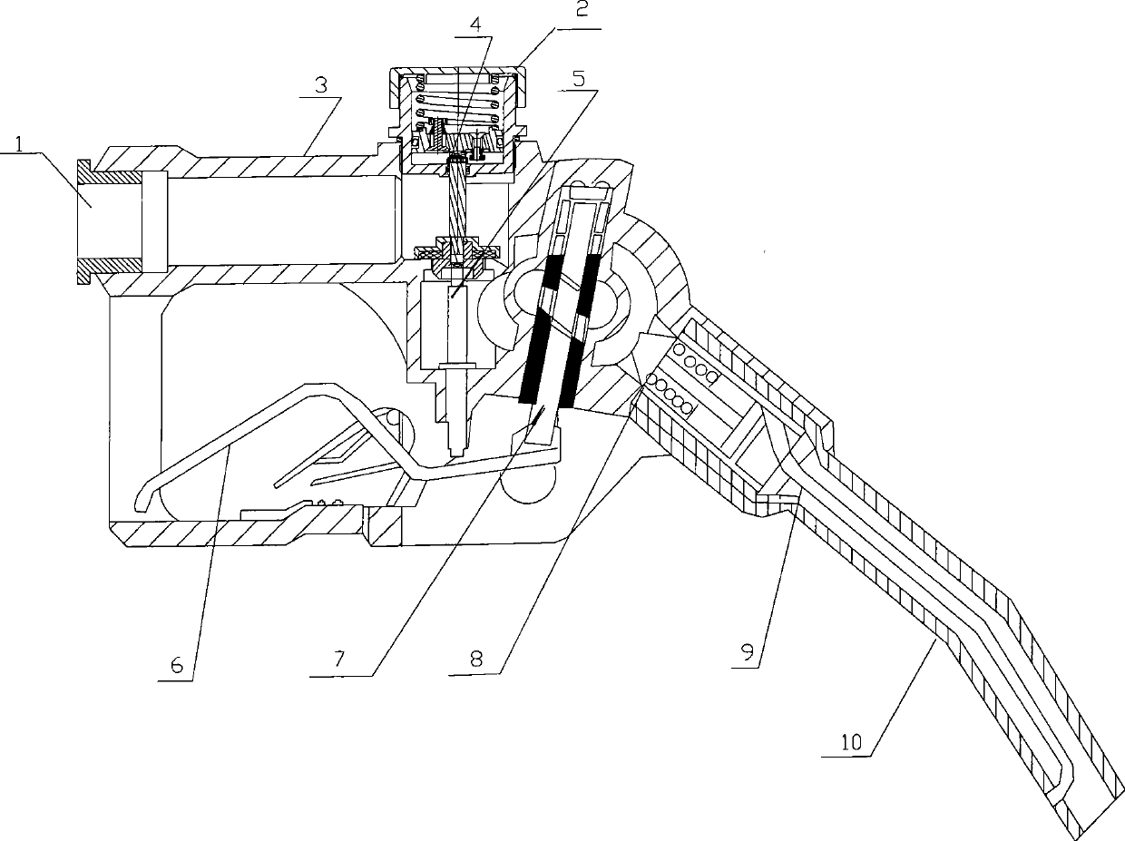
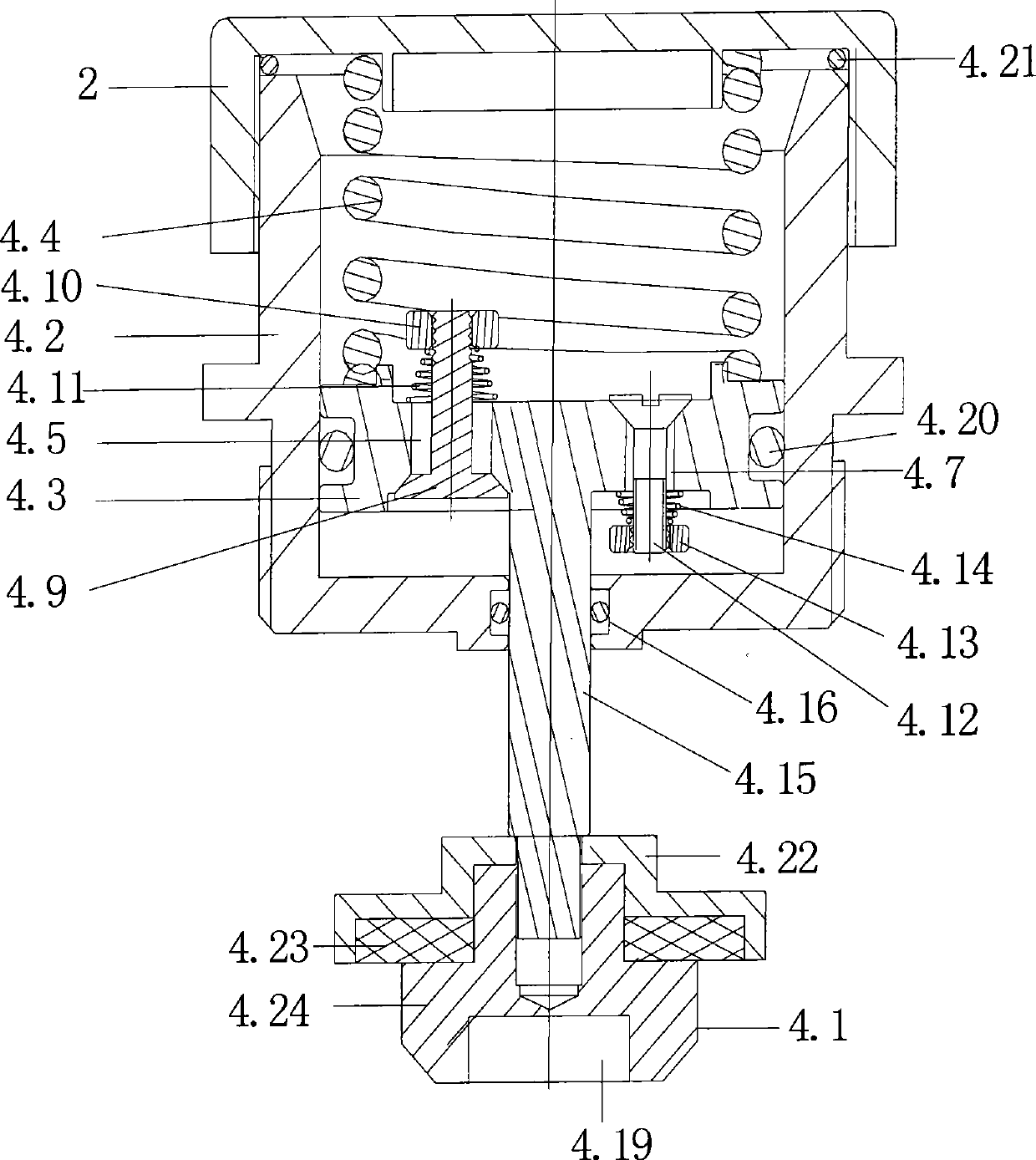
[0034] The structure of the fuel filler gun of the present invention is as figure 1 As shown, it consists of oil inlet 1, gun body 3, gun body cover 2, control valve 4, ejector rod 5, control handle 6, self-control lever 7, vacuum valve 8, vent pipe 9, and oil outlet pipe 10. The structure of the control valve 4 is as follows figure 2 As shown, it is composed of main valve 4.1, piston cylinder 4.2, piston 4.3 and the spring 4.4 whose two ends respectively resist the lower end surface of the gun body cover 2 and the upper end surface of the piston 4.3. The gun body cover 2 and the piston cylinder 4.2 are threadedly connected. An O-ring 4.21 is provided between the body cover 2 and the piston cylinder 4.2. The lower end surface of the gun body cover 2 is provided with a boss on which one end of the spring 4.4 is fixed, which is conducive to the fixed installation of the spring 4.4. The circumference of the piston 4.3 is provided with an annular groove, and the piston 4.3 passe...


PUM


Abstract

The invention discloses a fuel oil filling gun, which is characterized in that a control valve consists of a main valve, a piston cylinder, a piston which is positioned in the piston cylinder and closely matched with the inner wall of the piston cylinder, and a spring both ends of which are pressed against the lower end surface of a gun body cover and the upper end surface of the piston respectively; the piston is provided with at least two through holes, and unidirectional plugs are arranged in the through holes; the unidirectional plugs comprise two unidirectional plugs with opposite flow directions; the piston cylinder is provided with a hole for a piston rod fixedly connected with the lower surface of the piston to pass through, and the piston rod is fixedly connected with the main valve; and the bottom end of the main valve is provided with a bottom hole which is pressed against the top end of a mandril connected with a control handle. The fuel oil filling gun improves the control valve, can perform stepless regulation on the water hammer pressure peak during the gun closing, and greatly reduce the water hammer.

Description

technical field [0001] The invention relates to a fuel filling gun, in particular to a fuel filling gun used on a fueling machine at a gas station. Background technique [0002] In the hydraulic system of the oil dispenser, due to the drastic change of the fluid flow rate in the pipeline, a series of rapid hydraulic shock phenomena in which the pressure alternately rises and falls is called water hammer. The water hammer occurs because when the liquid flow stops suddenly, due to the action of the flowing liquid and the inertia of the moving parts, its kinetic energy becomes a high-pressure wave starting from the stop point, which is transmitted back and forth along the piping system at a speed close to the speed of sound , causing a high pressure in the system instantaneously. Under normal working conditions, the oil pressure in the fuel dispenser is about 0.1-0.3MPa, but when the fuel dispenser pump starts and stops, and the refueling gun is closed, the experimental result...

Claims


Application Information

Patent Timeline
IPC IPC(8): B67D5/373B67D7/48
Inventor 屈小根叶传春彭惠惠
Owner TOKHEIM HENGSHAN TECH GUANGZHOU
Why Eureka
Try Eureka