Supercharge Your Innovation With Domain-Expert AI Agents!

Optical pickup and optical disc device

A technology for optical pickups and optical devices, which is applied in beam guiding devices, optical recording heads, recording/reproducing with optical methods, etc., and can solve problems such as increased number of components, increased cost, and complex optical systems

Inactive Publication Date: 2009-05-27
SONY GRP CORP
View PDF1 Cites 2 Cited by
  • Summary
  • Abstract
  • Description
  • Claims
  • Application Information

AI Technical Summary

Problems solved by technology

[0024] However, with the optical pickup 160 shown in FIG. 13, by providing two detectors including light receiving elements, the number of components increases, thus causing problems from the viewpoints of cost reduction and size reduction.
That is, in the case of such an optical disc 160, for example, adopting these two detectors causes an increase in cost, and uses a device such as a beam splitter for separating and inputting beams corresponding to these detectors, and uses A plurality of parts such as a multi-lens serving as a magnification conversion lens for converging each light beam on the light-receiving element of each detector, and laying wiring from two places complicates the configuration, resulting in Problems, such as overall configuration becomes complicated, and also hinders reduction in device size, etc.
[0025] Thus, with the above-mentioned optical pickup shown in FIGS. 12 and 13, there is a problem in that the number of components increases and the optical system becomes complicated.
Meanwhile, providing a plurality of objective lenses or light-receiving elements causes problems such as increasing the process of adjusting these components, taking a lot of time for manufacturing the optical pickup, the configuration of the device becoming complicated, and preventing size reduction

Method used


Image

  • Optical pickup and optical disc device
  • Optical pickup and optical disc device
  • Optical pickup and optical disc device

Examples


Embodiment Construction

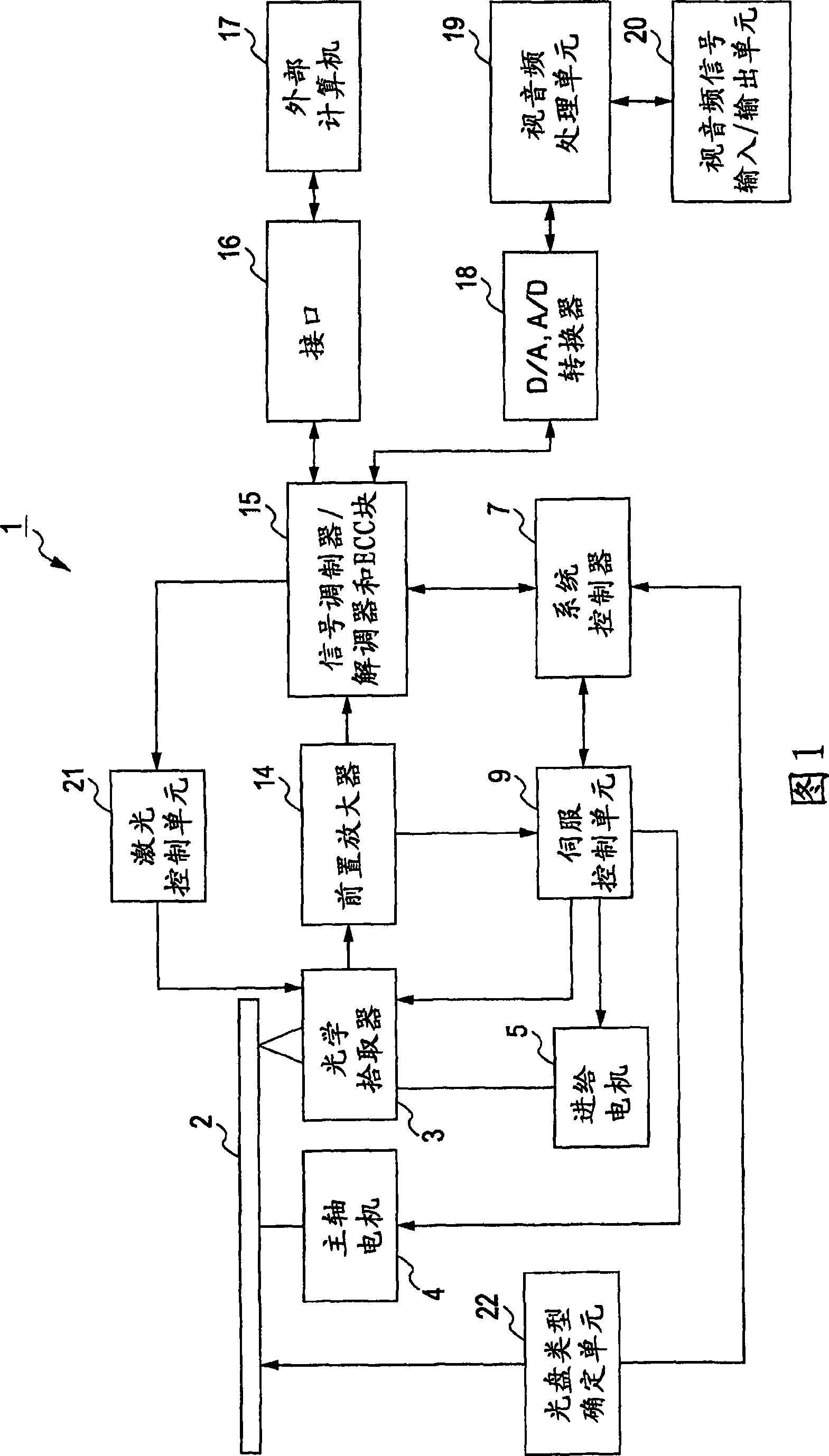
[0044] Hereinafter, an optical disc device employing an optical pickup to which an embodiment of the present invention is applied will be described with reference to the drawings.

[0045] As shown in FIG. 1, an optical disc device 1 to which an embodiment of the present invention is applied includes: an optical pickup 3 for performing recording / reproduction of information on an optical disc 2, a spindle motor 4 serving as a drive unit for rotationally operating the optical disc 2 , and a feed motor (or stepping motor) 5 for moving the optical pickup 3 in the radial direction of the optical disc 2. The optical disk drive 1 is an optical disk device realizing compatibility between three standards in which recording and / or playback of information can be performed on an optical disk in which recording layers are layered and three kinds of optical disks having different formats.

[0046] For example, the optical disc used here is: an optical disc using a semiconductor laser with a...


PUM

PropertyMeasurementUnit
wavelengthaaaaaaaaaa

Abstract

The invention provides an optical pickup and an compact disc device having the same. An optical pickup for performing recording and / or playback of information by selectively irradiating the corresponding wavelength optical beam to first through third optical discs having a protection layer with different thickness, includes emission units for emitting first-wavelength through third-wavelength optical beams corresponding to the respective optical discs respectively, a condensing optical device for condensing each wavelength optical beam on an optical disc signal recording face, a divergence angle transformation device, which can be moved in the optical axis direction, for transforming the divergence angle of each wavelength optical beam according to the moved position in the optical axis direction so as to obtain a predetermined divergence angle, and a detector having a common light receiving unit for receiving each wavelength optical beam separated by an optical path separating unit and returned, with the condensing optical device condensing each wavelength optical beam on the corresponding optical disc signal recording face appropriately.

Description

[0001] Cross References to Related Applications [0002] The present application contains subject matter related to Japanese Patent Application JP2007-303608 filed in the Japan Patent Office on Nov. 22, 2007, the entire content of which is hereby incorporated by reference. technical field [0003] The present invention relates to an optical pickup for performing recording and / or playback of information signals on three different types of optical discs, and an optical disc device using the same. Background technique [0004] In recent years, an optical disc capable of high-density recording (hereinafter, referred to as a "high-density recording optical disc") has been proposed as a next-generation optical disc format in which recording / reproduction of signals is performed by using a blue-violet semiconductor laser with a wavelength of about 405 nm. Beam execution. An example of such a high-density recording optical disc has been proposed in which a configuration in which a p...

Claims


Application Information

Patent Timeline
Patent Type & Authority Applications(China)
IPC IPC(8): G11B7/135G11B7/125
CPCG11B7/1374G11B7/1353G11B2007/0006G11B7/1275G11B7/13922G11B7/09
Inventor 金田一贤遊马嘉人高桥一幸
Owner SONY GRP CORP
Features
  • R&D
  • Intellectual Property
  • Life Sciences
  • Materials
  • Tech Scout
  • Unparalleled Data Quality
  • Higher Quality Content
  • 60% Fewer Hallucinations
Learn More