Drive control method of hybrid power drive system
A drive system and hybrid technology, which is applied to the arrangement of multiple different prime movers and power plants of hybrid vehicles and general power plants, can solve problems such as complex control methods, meet the demand power, and achieve maximum energy efficiency. the effect of using
- Summary
- Abstract
- Description
- Claims
- Application Information
AI Technical Summary
Problems solved by technology
Method used
Image

Examples
no. 1 example
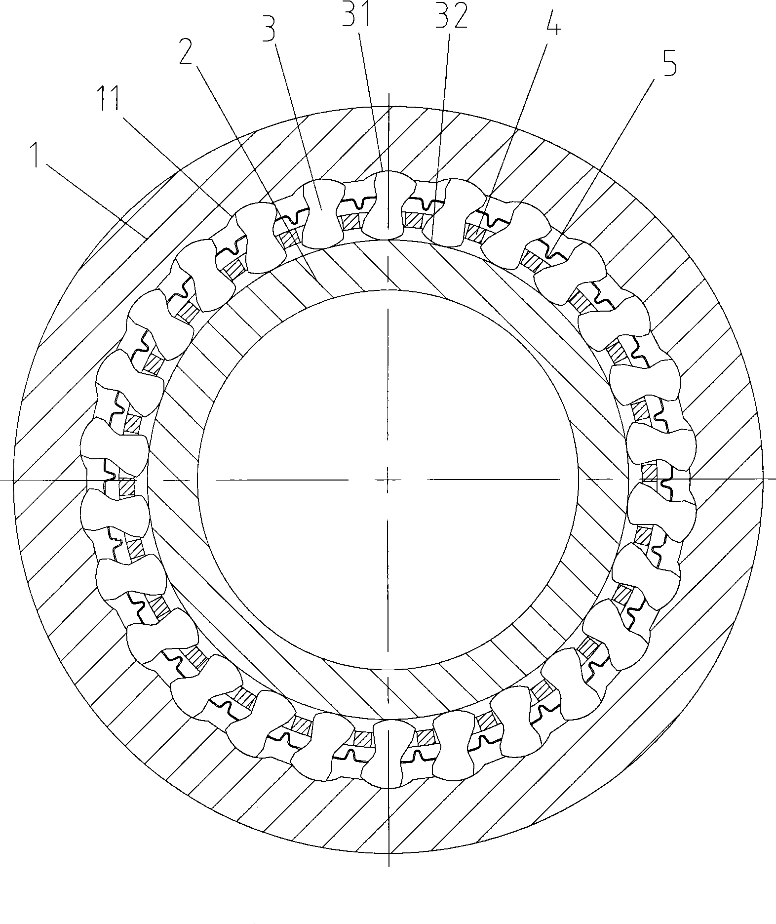
[0033] figure 1 is a sectional view of the three-state overrunning clutch according to the first embodiment of the present invention. The three-state overrunning clutch includes an outer ring 1, an inner ring 2, and a plurality of sprags 3 located between the outer ring 1 and the inner ring 2, which are located between the outer ring 1 and the inner ring 2 and hold the plurality of wedges through holding holes. A cage 4 for the wedge 3 . The first working surfaces 31 of the plurality of wedges 3 permanently contact the working surface of the outer ring 1 , and the second working surfaces 32 of the plurality of wedges 3 can contact or leave the inner ring 2 through rotation. working surface.
[0034] Specifically, the working surface of the outer ring 1 has a plurality of arc grooves 11, and each arc groove 11 is matched with the first working surface 31 of a corresponding wedge 3, and the first The working surface 31 is held in the arc groove 11 .
[0035] Such as Figure...
no. 2 example
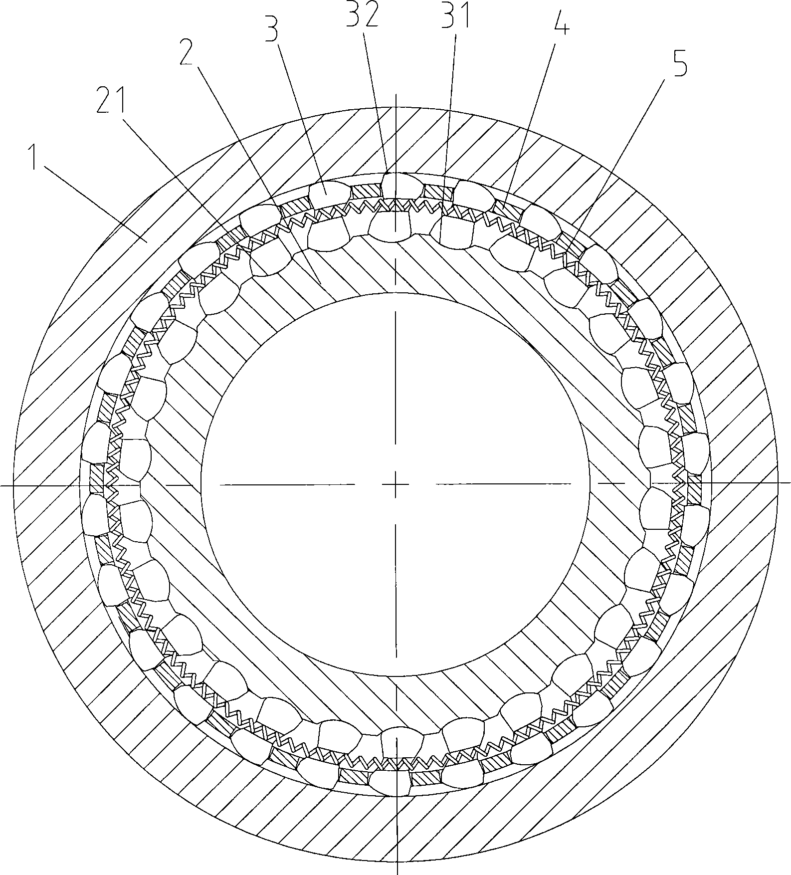
[0046] figure 2 Shown is a three-state overrunning clutch according to a second embodiment of the invention. Compared with the above-mentioned first embodiment, the difference is that: an arc groove 21 is provided on the working surface of the inner ring 2, and the first working surface 31 of the wedge 3 is also held in the arc groove 21, so that by holding The frame 4 can rotate the wedge 3 around its first working surface 31, and its working method is the same as that of the above-mentioned first embodiment.
[0047] In addition, in this second embodiment, the pre-tension spring 5 can simply use a contracted coil spring, the coil spring 5 passes through the through hole provided in the wedge 3, and the first working surface 31 of the wedge 3 Firmly held in the arc groove 21, and through the design of the position of the through hole on the wedge 3, the pre-tightening spring 5 can make the wedge 3 have a tendency to rotate towards the wedging direction.
no. 3 example
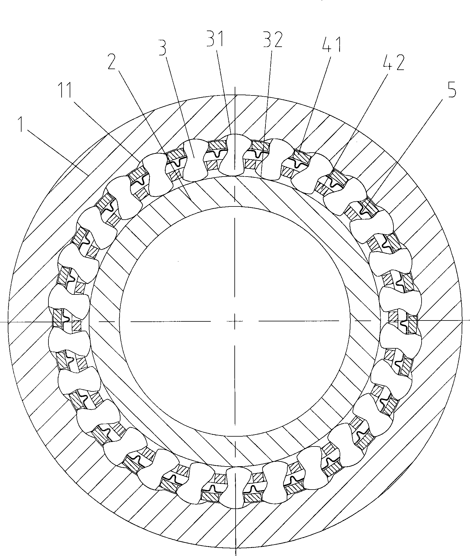
[0049] image 3 Shown is a three-state overrunning clutch according to a third embodiment of the present invention. Compared with the first embodiment above, the difference is that the cage 4 is a double cage structure, including an outer cage 41 and an inner cage 42 . Through this double cage structure, the bearing capacity of the three-state overrunning clutch of the present invention can be improved and its service life can be prolonged.
[0050] Wherein the plurality of tabs 6 protruding outward in the axial direction from the inner cage 42 are the same as the first embodiment. When the inner cage 42 rotates relative to each other, the outer cage 41 can rotate correspondingly with the wedge 3 without affecting the rotation of the wedge 3 .
PUM
 Abstract
Description
Claims
Application Information
 - R&D
- Intellectual Property
- Life Sciences
- Materials
- Tech Scout
- Unparalleled Data Quality
- Higher Quality Content
- 60% Fewer Hallucinations
Browse by: Latest US Patents, China's latest patents, Technical Efficacy Thesaurus, Application Domain, Technology Topic, Popular Technical Reports.
© 2025 PatSnap. All rights reserved.Legal|Privacy policy|Modern Slavery Act Transparency Statement|Sitemap|About US| Contact US: help@patsnap.com