Optical fiber current sensing device used for monitoring subway stray current

A technology of optical fiber current sensing and stray current, which is applied in the direction of measuring devices, measuring current/voltage, voltage/current isolation, etc., can solve the problem of poor long-term stability of reference electrode potential, limited life of long-term reference electrode, polarization Potential measurement errors and other problems, to overcome the difficulties of alignment and adjustment, good engineering application prospects, and the effect of measuring frequency bandwidth

Inactive Publication Date: 2009-06-03
CHINA UNIV OF MINING & TECH
View PDF0 Cites 15 Cited by
  • Summary
  • Abstract
  • Description
  • Claims
  • Application Information

AI Technical Summary

Problems solved by technology

[0003] (1) Metal corrosion is the result of long-term accumulation, and the life of the long-term reference electrode is limited. After several years, its measurement effect will be affected;
[0004] (2) The key to long-term stability of the buried reference electrode potential is to have a suitable ion-enriched filler and a surrounding environment that is suitable for electrode work and can prevent drying, otherwise, the long-term stability of the reference electrode potential will be poor. Difference
[0005] (3) There is an IR drop in the monitoring of the polarization potential, and the existence of the IR drop will bring errors to the measurement of the polarization potential. When there is a stray current disturbance, it is difficult to eliminate the influence of the IR drop

Method used


Image

  • Optical fiber current sensing device used for monitoring subway stray current
  • Optical fiber current sensing device used for monitoring subway stray current
  • Optical fiber current sensing device used for monitoring subway stray current

Examples


Embodiment Construction

[0025] The present invention will be further described in detail below in conjunction with the accompanying drawings and embodiments.

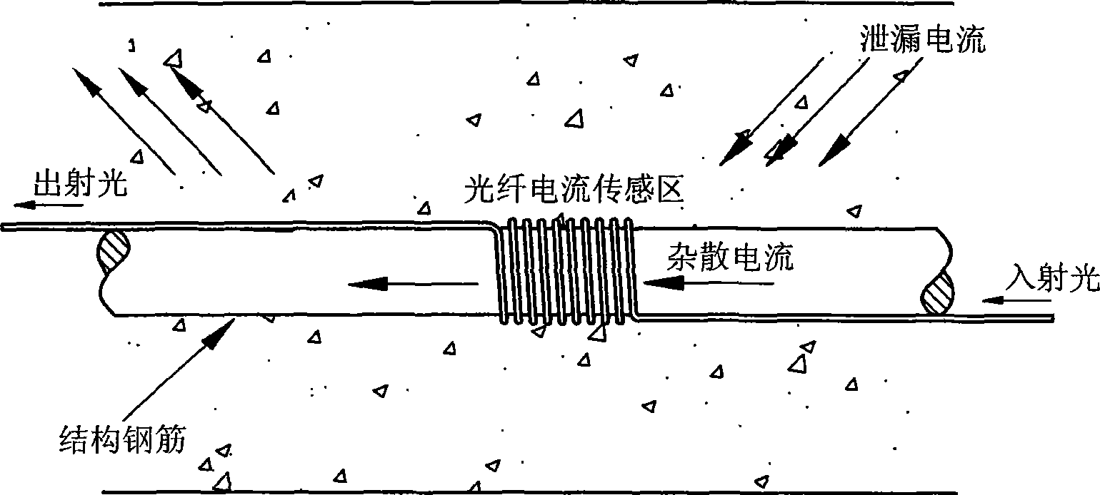
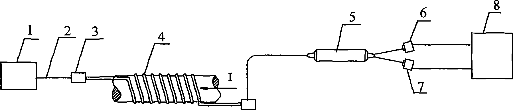
[0026] In order to realize the above-mentioned optical fiber current sensing method, the sensing device of the present invention consists of a highly stable polarization-adjustable light source 1, a transmission optical fiber 2, an optical fiber movable connector 3, an optical fiber current sensing head 4, a polarization beam splitter 5, a photoelectric Detectors 6, 7 and a signal processor 8 are composed. The sensing process is realized in this way: the polarized light emitted by the high-stability polarization-adjustable light source 1 is coupled into the fiber-optic current sensing head 4 through the transmission fiber 2 and the fiber-optic active connector 3, and the polarized light passes through the fiber-optic current surrounding the current-carrying conductor. When the sensor head 4 is affected by the Faraday rotation optical effect, t...


PUM


Abstract

The invention discloses an optical fiber current sensing method used for monitoring subway stray current and a sensing device thereof. Light-transmitting parts and sensing parts in the optical fiber current sensing device adopted by the invention are connected by all-fiber. The measurement results of the existing subway stray current monitoring method which is based on polarization potential monitoring are affected by factors and evaluated in a non-directviewing way. The invention is based on faraday effect, utilizes polarization property of optical fiber and indirectly measures current by measuring faraday rotation angle in the optical fiber, thereby overcoming the disadvantages of the traditional stray current monitoring method. The method has the prominent advantages that system test sensitivity can be adjusted according to specific conditions so as to be suitable for measuring current with different ranges. In the invention, the all-fiber is used for transmitting, thereby ensuring simple light path and good insulating property; closed circuit integral of a magnetic filed generated by current is detected by the sensing device, so that the measurement results are difficult to be affected by a stray field; the measurement frequency band is wide, and the dynamic range is wide, therefore, the invention has good project application prospect.

Description

technical field [0001] The invention relates to an optical fiber current sensing method and a sensing device for monitoring stray currents in subways, in particular to a method and a device for realizing sensing and measuring current by utilizing the Faraday rotation optical effect. Background technique [0002] At present, the monitoring methods adopted by countries around the world for the stray current of subways are generally the above-mentioned method based on polarization potential monitoring. In the initial stage of subway construction, a permanent reference electrode (long-term Cu / CuSO4) is buried, and the buried metal structure and The potential difference between the reference electrodes is used to reflect the disturbance and corrosion of the subway stray current. This method has the following problems: [0003] (1) Metal corrosion is the result of long-term accumulation, and the life of the long-term reference electrode is limited. After several years, its measure...

Claims


Application Information

Patent Timeline
Patent Type & Authority Applications(China)
IPC IPC(8): G01R19/00G01R15/24
Inventor 李威蔡文娟王禹桥
Owner CHINA UNIV OF MINING & TECH
Why Eureka
Try Eureka