Polishing liquid feeding pipe and chemical mechanical polishing device
A technology of grinding fluid and supply tube, applied in grinding/polishing equipment, metal processing equipment, manufacturing tools, etc., can solve the problems of semiconductor device yield decline, precipitation, crystallization, etc.
- Summary
- Abstract
- Description
- Claims
- Application Information
AI Technical Summary
Problems solved by technology
Method used
Image
Examples
Embodiment 1
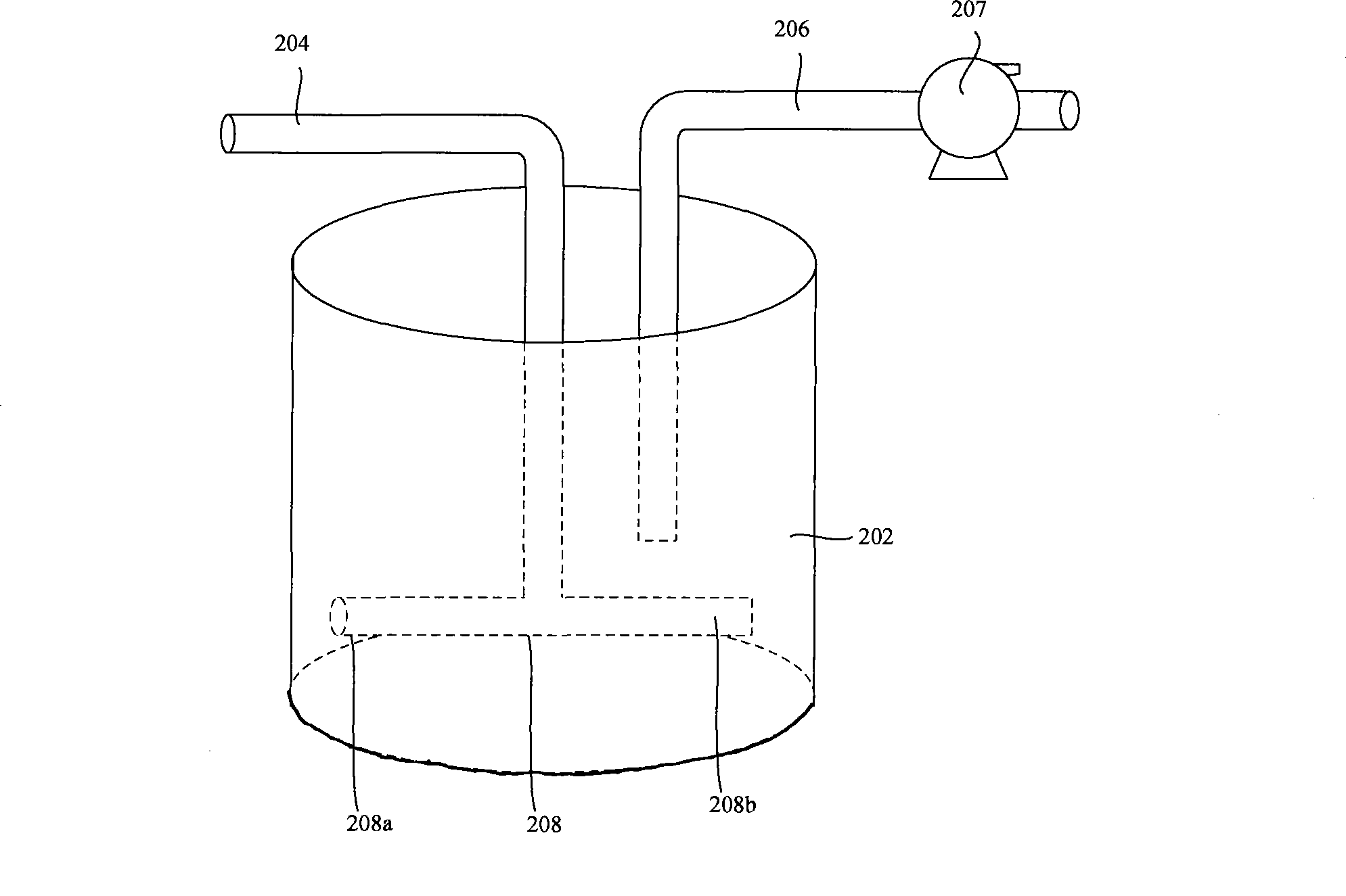
[0053] image 3 It is a perspective view of the first embodiment of the grinding liquid supply pipeline of the present invention. Please refer to image 3 The grinding liquid supply device includes a grinding liquid container 202 for holding the grinding liquid, a first pipeline 204 for inputting the grinding liquid to the grinding liquid container 202, a water tank that communicates with the first pipeline 204 and is positioned under the liquid surface of the grinding liquid container 202. The horizontal pipe 208 and the second pipeline 206 for outputting the grinding liquid from the grinding liquid container 202 to the outside.
[0054] Wherein, one end of the second pipeline 206 is connected with the grinding liquid container 202 . The other end of the second pipeline 206 may be connected to a grinding device (not shown), and a transport pump 207 may also be provided on the second pipeline 206 .
[0055] One end of the first pipeline 204 can be connected to the grinding ...
Embodiment 2
[0069] Figure 5 It is a perspective view of the second embodiment of the grinding liquid supply pipeline of the present invention.
[0070] Please refer to Figure 5 The grinding liquid supply device includes a grinding liquid container 202 for holding the grinding liquid, a first pipeline 204 for inputting the grinding liquid to the grinding liquid container 202, a water tank that communicates with the first pipeline 204 and is positioned under the liquid surface of the grinding liquid container 202. The horizontal pipe 208 and the second pipeline 206.
[0071] Wherein, one end of the second pipeline 206 is connected with the grinding liquid container 202 . The other end of the second pipeline 206 may be connected to a grinding device (not shown), and a transport pump 207 may also be provided on the second pipeline 206 .
[0072] One end of the first pipeline 204 can be connected to the grinding liquid supply source (not shown), and the other end can communicate with the ...
Embodiment 3
[0087] The end of the first pipeline extending below the liquid level of the grinding fluid in the grinding fluid container can be connected with two horizontal tubes, and the two horizontal tubes intersect, and at the intersection with the first pipeline connected. , the others are the same as those in the first embodiment, and will not be repeated here.
[0088] The end of the first pipeline of the supply pipeline in the second embodiment extending to below the liquid level of the grinding liquid in the grinding liquid container may also have two horizontal tubes, and the two horizontal tubes intersect. The intersection part communicates with the first pipeline. I won't go into details here.
[0089]In other embodiments, there may be three or more horizontal tubes, which will not be repeated here.
[0090] The invention also provides a chemical mechanical polishing device.
[0091] Figure 7 is a perspective view of an embodiment of the chemical mechanical polishing app...
PUM
| Property | Measurement | Unit |
|---|---|---|
| Angle | aaaaa | aaaaa |
| Length | aaaaa | aaaaa |
| Bending angle | aaaaa | aaaaa |
Abstract
Description
Claims
Application Information
 - R&D
- Intellectual Property
- Life Sciences
- Materials
- Tech Scout
- Unparalleled Data Quality
- Higher Quality Content
- 60% Fewer Hallucinations
Browse by: Latest US Patents, China's latest patents, Technical Efficacy Thesaurus, Application Domain, Technology Topic, Popular Technical Reports.
© 2025 PatSnap. All rights reserved.Legal|Privacy policy|Modern Slavery Act Transparency Statement|Sitemap|About US| Contact US: help@patsnap.com


