Ultra-resolution dual shaft differential confocal measurement method and device

A two-axis differential confocal and super-resolution technology, applied in the direction of measuring devices, optical devices, instruments, etc., can solve the problem that the size of the objective lens and the resolution of the system cannot be well balanced, and there is no absolute position aiming and bipolar Tracking, which is not conducive to eliminating the common mode noise of the light intensity drift of the light source, etc., to achieve the effect of improving system resolution, improving linear range, and improving anti-interference ability

Inactive Publication Date: 2009-06-17
BEIJING INSTITUTE OF TECHNOLOGYGY
View PDF4 Cites 16 Cited by
  • Summary
  • Abstract
  • Description
  • Claims
  • Application Information

AI Technical Summary

Problems solved by technology

[0006] To sum up, the measurement methods based on the traditional coaxial confocal microscopy technology generally have the problem that the size of the objective lens and the system resolution cannot be well balanced. If the system resolution is improved by increasing the numerical aperture of the objective lens, it will The size of the objective lens increases, the working distance of the system decreases, and it is not easy to miniaturize
The dual-axis structure that symmetrically arranges the illumination optical path and the measurement optical path on both sides of the normal of the measurement surface can effectively balance the space size of the entire confocal system, but the design of its single detector is still not conducive to eliminating the light intensity drift of the light source. Common mode noise such as electronic drift of detectors and detectors, and does not have the capabilities of absolute position targeting and bipolar tracking

Method used


Image

  • Ultra-resolution dual shaft differential confocal measurement method and device
  • Ultra-resolution dual shaft differential confocal measurement method and device
  • Ultra-resolution dual shaft differential confocal measurement method and device

Examples


Embodiment Construction

[0044] The present invention will be further described below in conjunction with drawings and embodiments.

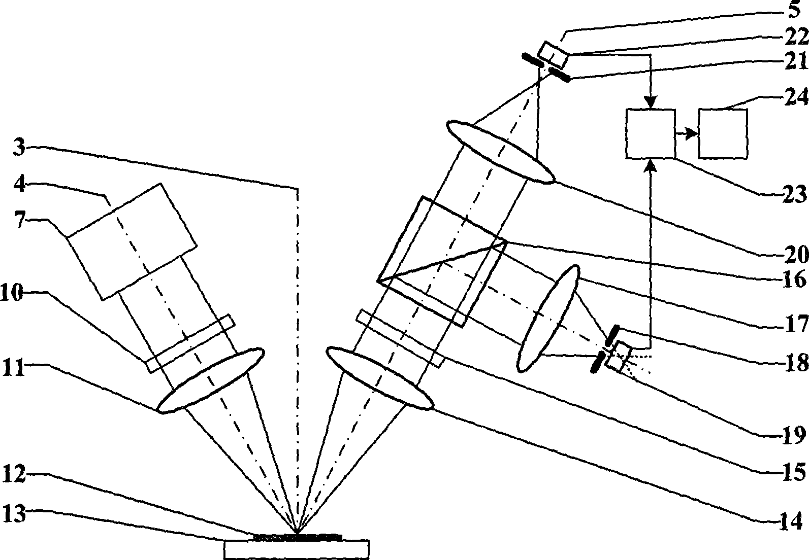
[0045] Such as image 3 As shown, a super-resolution two-axis differential confocal measurement method, the measurement steps are:

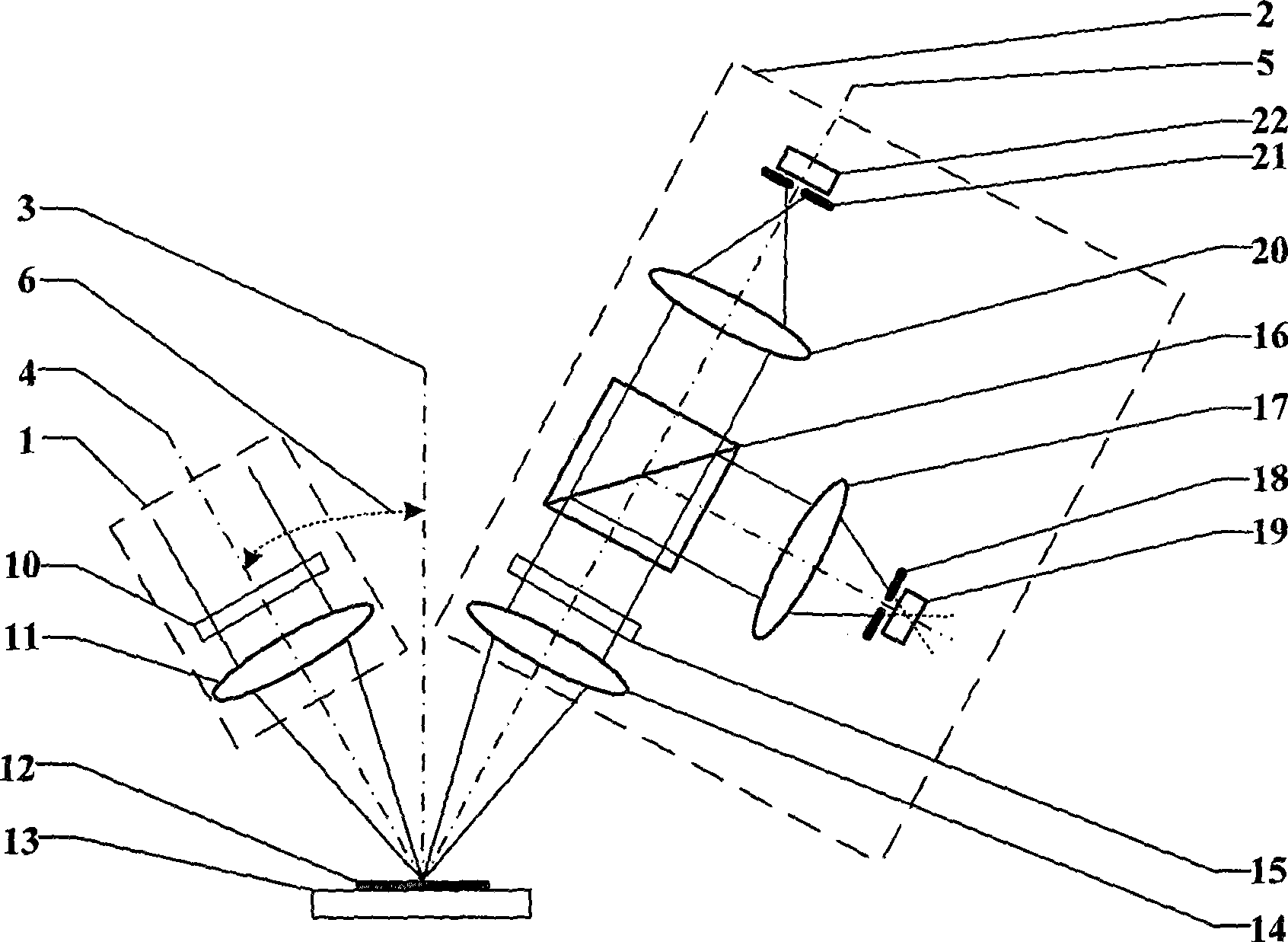
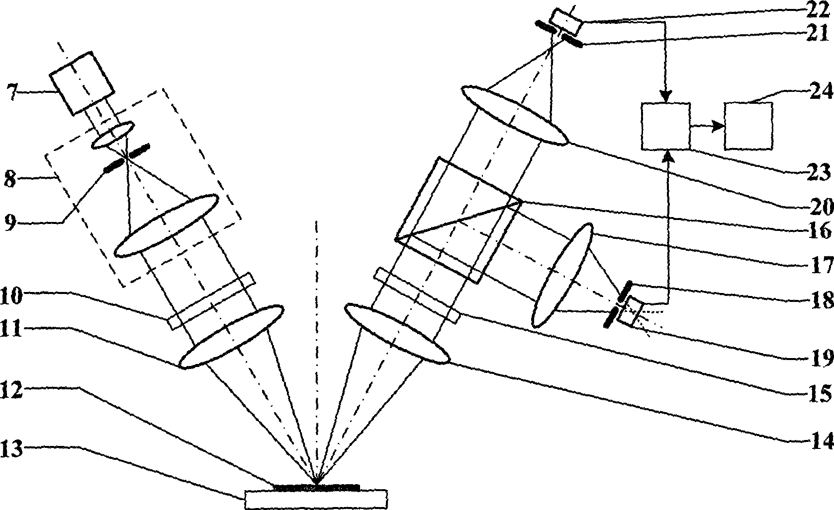
[0046] First, the light source 7 (wavelength λ) is turned on, and the outgoing light is expanded into parallel light through the beam expander system 8 containing the spatial filter pinhole 9, and the parallel light is filtered and shaped by the pupil filter 10 at the illumination end, and then focused by the illumination objective lens 11 The surface of the measured sample 12 placed on the micro-displacement worktable 13 is reflected into the measurement objective lens 14, emerges as parallel light, and is filtered and shaped by the pupil filter 15 at the measurement end.

[0047] The light beam emitted by the pupil filter 15 at the measuring end is divided into two beams by the beam splitter 16, passes through the first collecting mirro...


PUM


Abstract

The invention belongs to the technical field of optical precise measurement and relates to a super-resolution double-shaft differential confocal measuring method and a super-resolution double-shaft differential confocal measuring device. In the method and the device, pupil filtering technology is fused in a double-shaft confocal measuring structure, and a differential treatment method is used for receiving a measured light beam and carrying out treatment, thereby achieving the aims of improving resolution, expanding working distance, improving anti-interference capability and improving linear range. The invention can be used for precise measurement in such fields as micro-electronics, materials, industrial precise detection, biomedicine, etc.

Description

technical field [0001] The invention belongs to the technical field of optical precision measurement and can be used for precision measurement in the fields of microelectronics, materials, industrial precision detection, biomedicine and the like. technical background [0002] American scholar M.Minsky first proposed the idea of ​​confocal microscope in 1957, and obtained the US patent in 1961, the patent number is US3013467. The confocal microscope places the point light source, point object, and point detector in corresponding conjugate positions, forming a point illumination and point detection microscopic imaging system with unique tomographic capabilities in optical microscopic imaging. [0003] The tomographic imaging capability of a confocal microscope is determined by the full width at half maximum (FWHM) of its axial response curve, and FWHM is proportional to the wavelength λ of the light wave and inversely proportional to the square of the numerical aperture NA of ...

Claims


Application Information

Patent Timeline
Patent Type & Authority Applications(China)
IPC IPC(8): G01B11/24G01B11/30
Inventor 赵维谦江琴邱丽荣沙定国
Owner BEIJING INSTITUTE OF TECHNOLOGYGY
Why Eureka
Try Eureka