Manufacturing method of optical film

A manufacturing method and optical film technology, applied in optics, optical components, nonlinear optics, etc., can solve the problems of conveyor belt slack, cannot fully avoid conveyor belt, slack, etc., and achieve the effect of improving flatness

Inactive Publication Date: 2009-06-17
NITTO DENKO CORP
View PDF2 Cites 2 Cited by
  • Summary
  • Abstract
  • Description
  • Claims
  • Application Information

AI Technical Summary

Problems solved by technology

However, especially when the rotation axis of the rubbing roller is inclined from a direction perpendicular to the film conveyance direction, there is still a problem that the belt slack and the influence of the belt slack cannot be sufficiently avoided.

Method used


Image

  • Manufacturing method of optical film
  • Manufacturing method of optical film
  • Manufacturing method of optical film

Examples


Embodiment

[0063] Hereinafter, the characteristics of the present invention will be further clarified by showing Examples and Comparative Examples.

[0064] Example

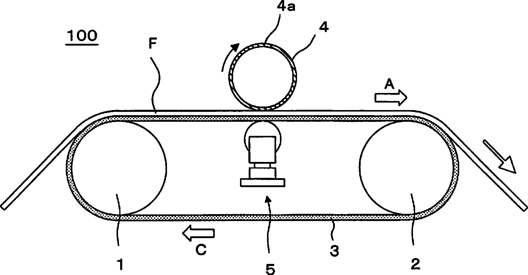
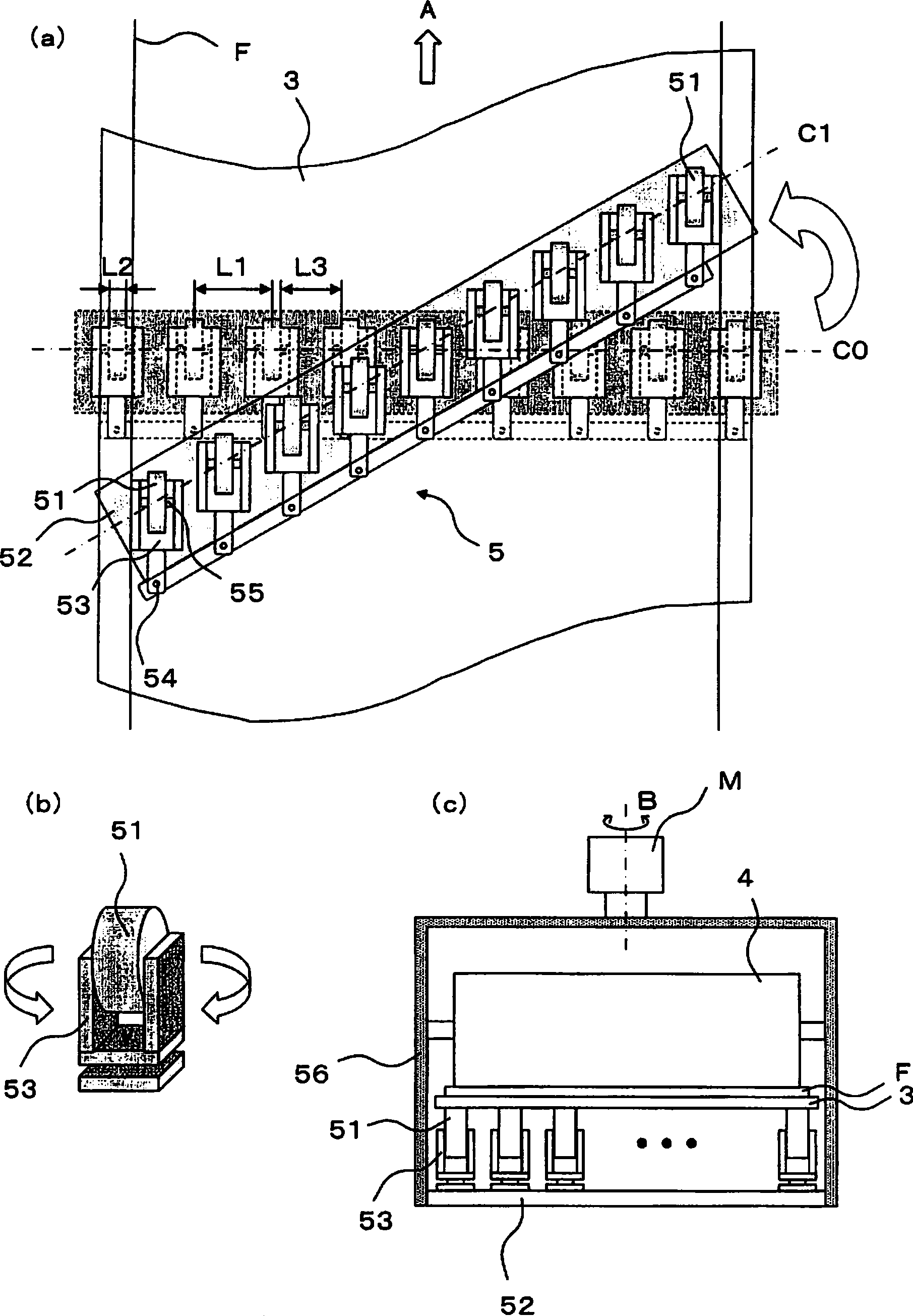
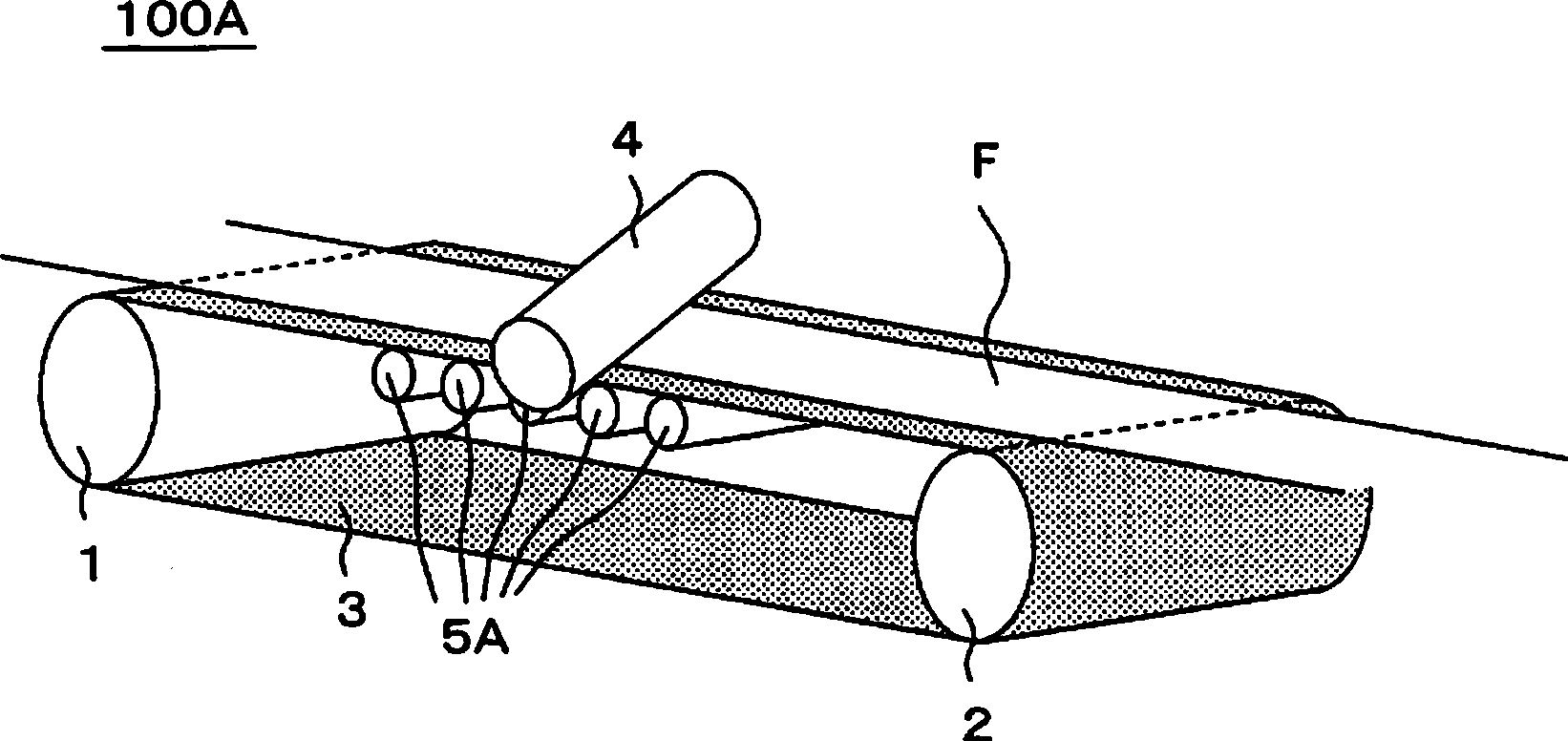
[0065] use figure 1 and figure 2 The rubbing treatment apparatus 100 shown performs a rubbing treatment on a cellulose triacetate film subjected to alkali treatment to a thickness of 40 μm. In addition, the polishing of the surface of the conveyor belt 3 is Ra=0.01 μm, the outer diameter of the driving rollers 1 and 2 is 550 mm, the conveying speed of the film is 5 m / min, the outer diameter of each backup roller 51 is 90 mm, and the adjacent each The center-to-center distance L1 in the rotation axis direction of the support rolls 51 was 80 mm, and the width L2 in the rotation axis direction of each support roll 51 was 30 mm. In addition, as the rubbing roller 4 , a roller having a radius (including the fleece 4 a ) of 76.89 mm and wound with a rayon fleece was used. The rotation axis of the rubbing roller 4 was incli...


PUM

PropertyMeasurementUnit
thicknessaaaaaaaaaa

Abstract

A method of manufacturing an optical film has a rubbing step for rubbing the surface of a long plastic film (F) by a rubbing roll (4) around which a napped fabric is wound, an application step for applying liquid crystalline molecules to the surface of the film having passed the rubbing step, and a fixation step for fixing the applied liquid crystalline molecules. The rubbing step has a backup roll mechanism (5) for supporting and conveying the film by the use of a conveyor belt (3) that has a metal surface and supporting the lower surface of the conveyor belt. The backup roll mechanism has backup rolls (51) individually rotated in the moving direction of the conveyor belt. The backup rolls are disposed immediately beneath the rubbing roll, along a straight line substantially in parallel with the rotating axis of the rubbing roll.

Description

technical field [0001] The present invention relates to a method for producing an optical film used for optical compensation, antireflection, etc. of a liquid crystal display device or the like. In particular, the present invention relates to a method for producing an optical film having uniform optical characteristics at low cost. Background technique [0002] Conventionally, various optical elements manufactured by coating and aligning a liquid crystal material on a base material are known. In the manufacturing process of such an optical element, in order to orient the liquid crystal material on the surface of the base material, for example, a rubbing treatment of rubbing the surface of the base material in one direction with a flannelette is generally performed. For example, when the optical element is a liquid crystal cell, rubbing treatment is performed on a unit-sized glass substrate as a base material. However, in the case of an optical element (optical film) using ...

Claims


Application Information

Patent Timeline
Patent Type & Authority Applications(China)
IPC IPC(8): G02B5/30G02F1/13363
CPCG02B5/3016G02F1/13363G02F1/13378G02F1/1337G02B5/30
Inventor 秦和也川本育郎米泽秀行土本一喜
Owner NITTO DENKO CORP
Why Eureka
Try Eureka