Wire rod bar blooming mill

A blanking machine and wire bar technology, applied in the direction of metal rolling stand, metal rolling mill stand, metal rolling, etc., can solve the problems of low product quality, limited forging ratio, limited product specifications, etc., and achieve equipment operation performance Low energy consumption, improved forging ratio, and advanced structure

Active Publication Date: 2009-06-24
CISDI HEAVY MACHINERY
View PDF0 Cites 24 Cited by
  • Summary
  • Abstract
  • Description
  • Claims
  • Application Information

AI Technical Summary

Problems solved by technology

However, due to the limited forging ratio of products rolled by continuous casting billets, the product specifications prod

Method used


Image

  • Wire rod bar blooming mill
  • Wire rod bar blooming mill
  • Wire rod bar blooming mill

Examples


Example Embodiment

[0017] The embodiments of the present invention will be further described below in conjunction with the accompanying drawings:

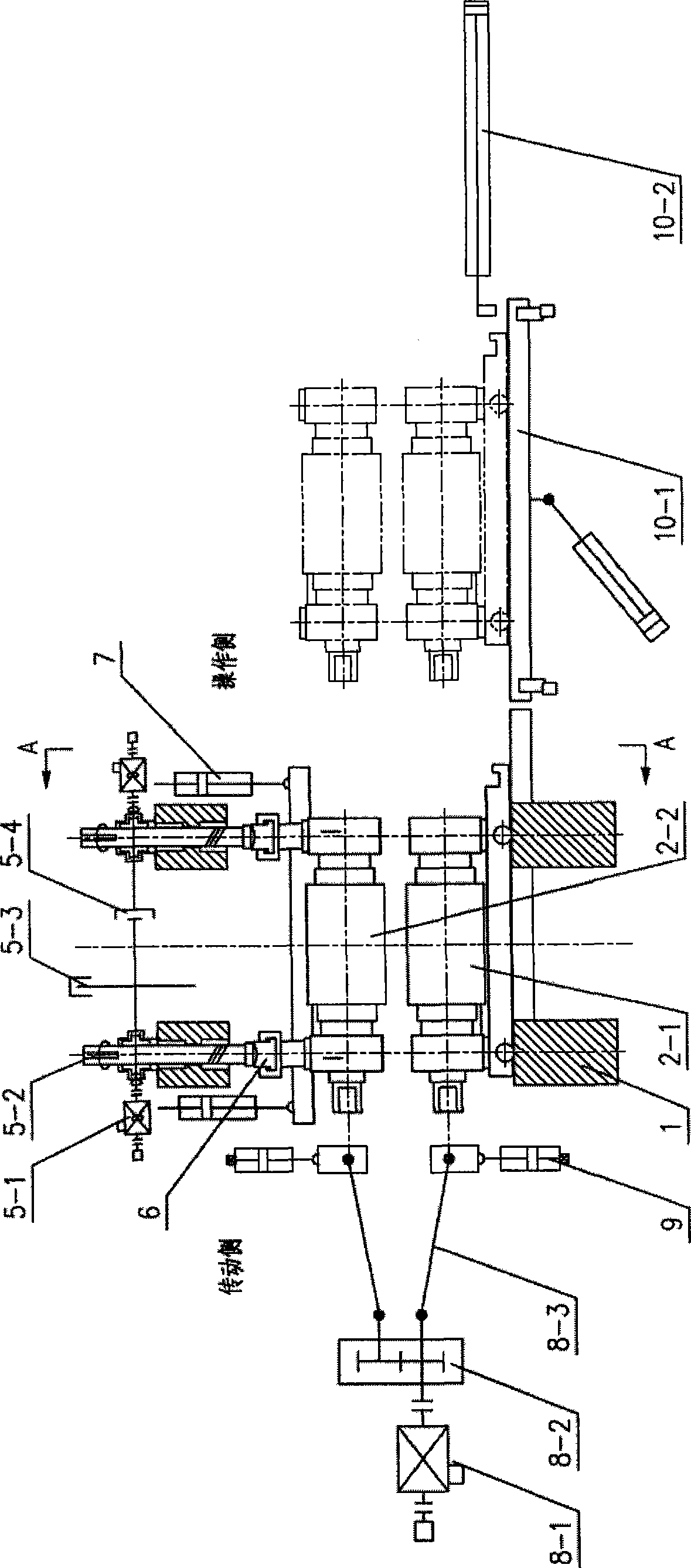
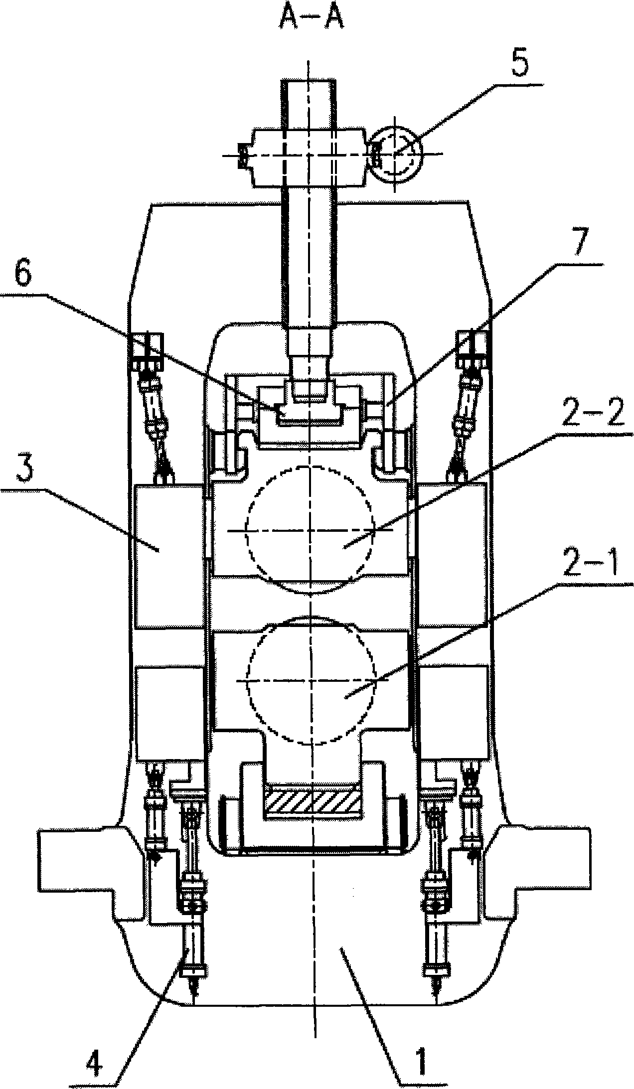
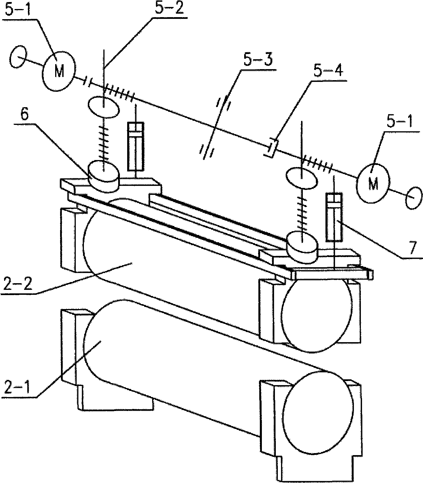
[0018] This device includes rolling mill housing assembly 1, work roll assembly 2, work roll locking device 3, work roll axis shift device 4, electric pressing device 5, anti-rolling jam hydraulic cylinder 6, upper work roll balance device 7, guide guard beam Device, main transmission device 8, shaft bracket 9, roller change device 10, hydraulic lubrication system and piping. The mill housing assembly 1 of the billeting mill is connected by the operating side and the transmission side housing through the cross beam and the bottom plate into a whole, and anchored on the foundation by anchor bolts; the work roll assembly 2 is through the work roll locking device 3 and the work roll axis shift device 4 Fixed in the rolling mill housing assembly 1, through the electric pressing device 5 can slide up and down in the rolling mill housing assembly 1 window; wor...


PUM


Abstract

The invention belongs to the technical field of metallurgy machinery, and in particular relates to a linear rod cogging mill. An upper working roller and a lower working roller are driven by a main transmission device to assemble and rotate, and roller seams are adjusted up and down by driving the upper working roller to assemble through a dynamoelectric press down device. Large continuous casting square blanks are rolled into needed small square blanks through two rollers of reversible rolling mills. The cogging mill can roll the large continuous casting square blanks into the needed small square blanks, improve the product quality, promote product grades, optimize and widen product structures, and improve the continuous casting output and the product yield of the whole factory, is not limited by the specifications of upstream continuous casting blanks, and improves the forging ratio. The cogging mill can be arranged in all newly built high-speed wire machine sets or wire reformation machine sets and in particular partial prior linear rod machine sets which can be reformed by utilizing the prior rolling mill transmission devices so as to save partial investment.

Description

technical field [0001] The invention belongs to the technical field of metallurgical machinery, and in particular relates to a blanking machine for rough rolling of wire and bar. technical background [0002] Wire rod is one of the important products of the iron and steel industry, which is widely used in various infrastructure construction, construction engineering construction and metal products industry. my country began to produce high-speed wire rods in 1987. At present, my country has become the country with the most high-speed wire rod production lines and the largest output in the world. [0003] Before the advent of continuous casting machines, wire rod production was based on casting steel ingots and heating the steel ingots to obtain qualified square billets before producing wire rods. Due to the high labor intensity, high environmental pollution, and high energy consumption in the processes of die casting and billet opening, after the successful use of continuou...

Claims


Application Information

Patent Timeline
IPC IPC(8): B21B1/02B21B31/24B21B31/00B21B31/08B21B33/00B21B31/02
Inventor 李轲余小军王勤闵建军李传刚李图学
Owner CISDI HEAVY MACHINERY
Why Eureka
Try Eureka