
Engineering machinery control system, engineering machinery and engineering machinery control method

A control system and engineering machinery technology, applied in the field of control, can solve the problems of hydraulic shock, high oil temperature and matching of hydraulic actuators, and achieve the effect of maintaining proper temperature, preventing excessive temperature rise, and reducing cycle frequency.

Inactive Publication Date: 2009-06-24
SANY HEAVY IND CO LTD (CN)
View PDF0 Cites 15 Cited by
  • Summary
  • Abstract
  • Description
  • Claims
  • Application Information

AI Technical Summary

Problems solved by technology

[0005] First, when the load of the hydraulic system is small, the engine drives the hydraulic pump at a constant speed, and the excess high-pressure oil returns through the relief valve, which reduces the efficiency of the construction machinery and increases the fuel consumption of the engine
[0006] Second, maintain a large flow rate of the hydraulic pump to speed up the circulation of the hydraulic oil, and the hydraulic oil in the hydraulic system will heat up quickly, which will easily lead to excessive oil temperature and affect the reliability and operability of the hydraulic system.
[0007] Third, when the hydraulic system transitions from the idling state to the running state, due to the sudden increase in the oil supply of the hydraulic pump, it will cause hydraulic shock to the hydraulic actuator and affect the operating performance of the construction machinery
[0008] In order to solve the above problems, in actual use, the operator can also manually adjust the engine speed many times. On the one hand, this method will affect the operator's control of the lever arm movement; The matching problem between the rotating speed of the driving hydraulic pump and the demand of the hydraulic system for high-pressure oil

Method used


Image

  • Engineering machinery control system, engineering machinery and engineering machinery control method
  • Engineering machinery control system, engineering machinery and engineering machinery control method
  • Engineering machinery control system, engineering machinery and engineering machinery control method

Examples


Embodiment 1

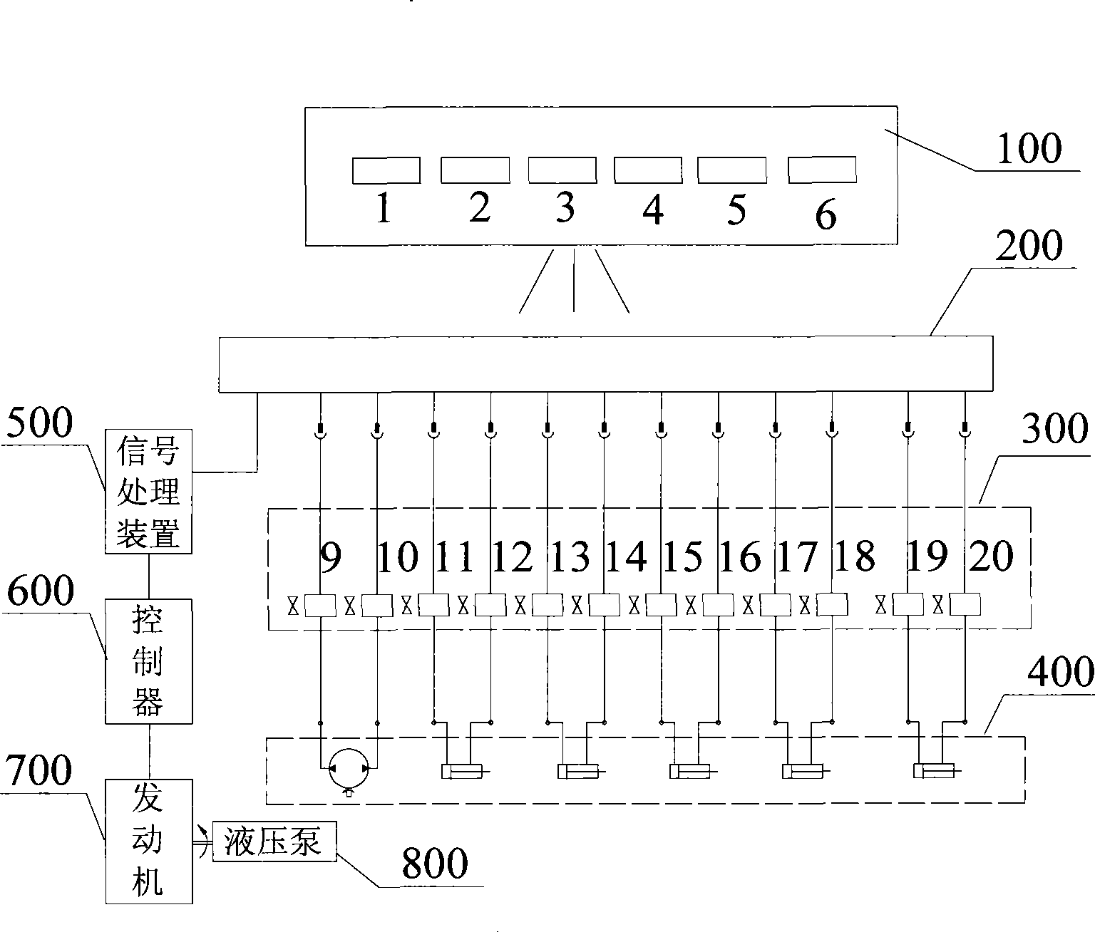
[0039] Embodiment 1 provides a control system for a concrete pump truck. The concrete pump truck includes a boom and a chassis. The boom consists of five sequentially articulated booms, and the relative movements between the booms are driven by corresponding hydraulic cylinders. The boom is installed on the chassis, and can be driven by a hydraulic motor to rotate around a vertical axis on the chassis to realize the circumferential adjustment of the boom angle.

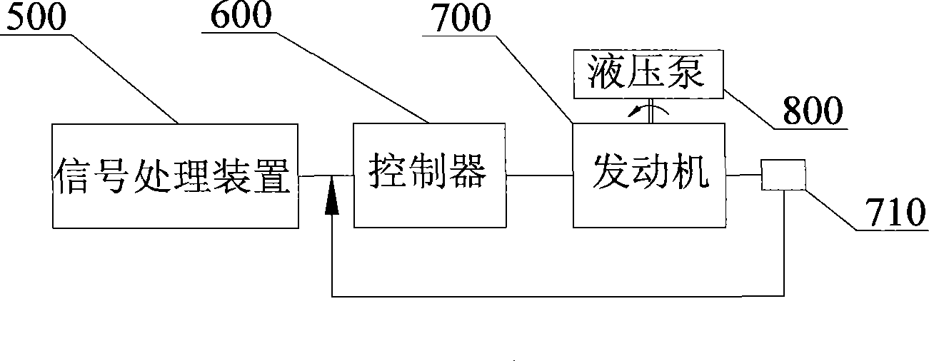
[0040] Such as figure 1 As shown, the control system includes a manipulation platform, a receiver 200, a proportional flow valve unit 300, a signal processing device 500 and a controller 600, the proportional flow valve unit 300 includes proportional flow valves 9-20, and the hydraulic actuator unit 400 includes The hydraulic motor driving the boom to rotate and the five hydraulic cylinders driving the boom to move; in addition, for the convenience of description, the figure also shows the engine 600 and the hydraulic...


PUM


Abstract

The invention discloses an engineering mechanical control system, comprising a manipulator, a signal generation pickup device and a proportional flow valve, wherein, the signal generation pickup device can generate control signals according to the adjustment range of the manipulator, and controls the flow rate of hydraulic oil passing through the proportional flow valve by the control signals; and the proportional flow valve can be connected in series between a hydraulic pump and a hydraulic actuating mechanism. The engineering mechanical control system also comprises a signal processing device and a controller, wherein, the signal processing device can generate rotating speed control signals; and the controller can control the output rotating speed of a power source according to the rotating speed control signals. Besides the control system, the invention also discloses engineering machinery and a control method thereof, wherein, the engineering mechanical control system and the engineering machinery with the control system can cause the output rotating speed of a power source driving a hydraulic pump to run to be matched with the required amount of high-pressure oil of the hydraulic system, and the energy consumption is reduced while the requirement of the driving force of the engineering machinery is satisfied.

Description

technical field [0001] The present invention relates to a control technology, in particular to a construction machinery control system, and also to a construction machinery with the construction machinery control system, and also to a construction machinery control method. Background technique [0002] At present, many construction machinery are equipped with a power system with an engine as the power source and a hydraulic system with a hydraulic pump as the power source. Enough high pressure oil. In actual use, the hydraulic system generally has two states: one is the running state; the other is the idling state. When the hydraulic system is in the running state, the high-pressure oil discharged by the hydraulic pump is sent to the corresponding hydraulic actuator through the hydraulic valve, and the hydraulic actuator is driven to perform the corresponding action to complete the corresponding work; when the hydraulic system is in the idling state, the hydraulic pump and ...

Claims


Application Information

Patent Timeline
IPC IPC(8): F15B21/02F15B21/00F15B13/02E04G21/02
Inventor 易小刚谭凌群左光群
Owner SANY HEAVY IND CO LTD (CN)
Learn More