
Method for manufacturing power decentralization and power centralization type transformer oil tank

A technology of transformer oil tank and power concentration, which is used in inductor/transformer/magnet manufacturing, transformer/inductor cooling, electrical components, etc., can solve the problems of inability to complete welding at one time, non-conformance, low production efficiency, etc., and achieve large-scale production. The effect of the production line operation, the control of welding stress and deformation, and the improvement of the production qualification rate

Inactive Publication Date: 2010-12-08
DATONG ELECTRIC LOCOMOTIVE OF NCR
View PDF4 Cites 0 Cited by
  • Summary
  • Abstract
  • Description
  • Claims
  • Application Information

AI Technical Summary

Problems solved by technology

In the welding process, there is no reasonable order for the welding of non-assembly accessories, four side wall panels and the base, so that in the welding process of non-assembly accessories that do not require high dimensional and position accuracy, and the four sides of the box The welding stress and deformation generated during the welding process of the wall plate and the base will affect the welding accuracy and quality of the assembly accessories such as the mounting seat and the oil pipe union. The welding stress and deformation are not easy to control, and the assembly accessories are greatly affected by the welding stress and deformation. The flatness of the installation seat and the oil line union pipe after welding cannot meet the requirements, which not only directly affects the product quality of the fuel tank, but also brings a great deal of trouble to the subsequent assembly and connection with the bottom of the locomotive and the assembly and connection with the pipeline of the locomotive. difficulty
Usually, in order to reduce the influence of welding deformation as much as possible, in the existing method, after the overall welding of the transformer oil tank is completed, it is usually necessary to perform flame correction according to the actual deformation size of each mounting seat and each oil pipe union that has been affected by welding deformation. After the stress relief process is repaired after welding, the process is relatively long, the production efficiency is low, and it is not easy to realize large-scale assembly line operations, which affects the manufacturing speed of the transformer oil tank; and the repair process is difficult to adjust, correct the mounting seat, and the oil circuit. The welding accuracy caused great troubles in the manufacturing process of the transformer oil tank, which affected the product pass rate of the oil tank, and also affected the assembly speed of the transformer oil tank and the locomotive and the pass rate of the locomotive.
Does not meet current high-quality, high-speed efficient manufacturing requirements
[0005] 2. In the existing methods of manufacturing power-dispersed and power-concentrated transformer oil tanks, when welding mounting seats, oil pipes, etc., it is necessary to simulate spot welding on the fuel tank carcass according to the theoretical positions of the mounting seats and oil pipes. , and wait until the transformer oil tank assembly can be welded, so it is impossible to complete the welding at one time, the process is relatively long, the production efficiency is low, and it is not easy to realize large-scale assembly line operations; and these assembly accessories are difficult to install due to individual welding The assembly and welding quality of the seat and all oil pipes increases the difficulty of assembly and connection between the mounting seat and the bottom of the locomotive, as well as the assembly and connection between the oil pipe and the locomotive pipeline, which does not meet the current high-quality, high-speed and efficient manufacturing requirements
[0006] 3. In the existing power dispersion and power concentration type transformer oil tank manufacturing methods, the processing of the mounting holes on the mounting base is generally carried out in the traditional single hole scribing process, which is not easy to ensure that the mounting base and the car body The processing accuracy of the connected mounting holes will make it difficult to assemble the transformer oil tank and the locomotive, the production efficiency will be low, and it will not be easy to realize large-scale assembly line operations, which will seriously affect the safety and reliability of the transformer oil tank after it is connected to the bottom of the locomotive. Properties such as sex and vibration damping affect the product qualification rate
[0007] It can be seen that in the manufacturing method of the power dispersion and power concentration type transformer oil tank in the prior art, it is true that the welding stress deformation in the welding operation process is difficult to control, and the product quality is greatly affected by the welding deformation; the process is relatively long, and the production efficiency is low. It is easy to realize large-scale assembly line operations; the product accuracy is not very ideal, and there are many problems such as high difficulty in assembling with locomotives, which do not meet the current high-quality, high-speed and efficient manufacturing requirements

Method used


Image

  • Method for manufacturing power decentralization and power centralization type transformer oil tank
  • Method for manufacturing power decentralization and power centralization type transformer oil tank
  • Method for manufacturing power decentralization and power centralization type transformer oil tank

Examples


Embodiment Construction

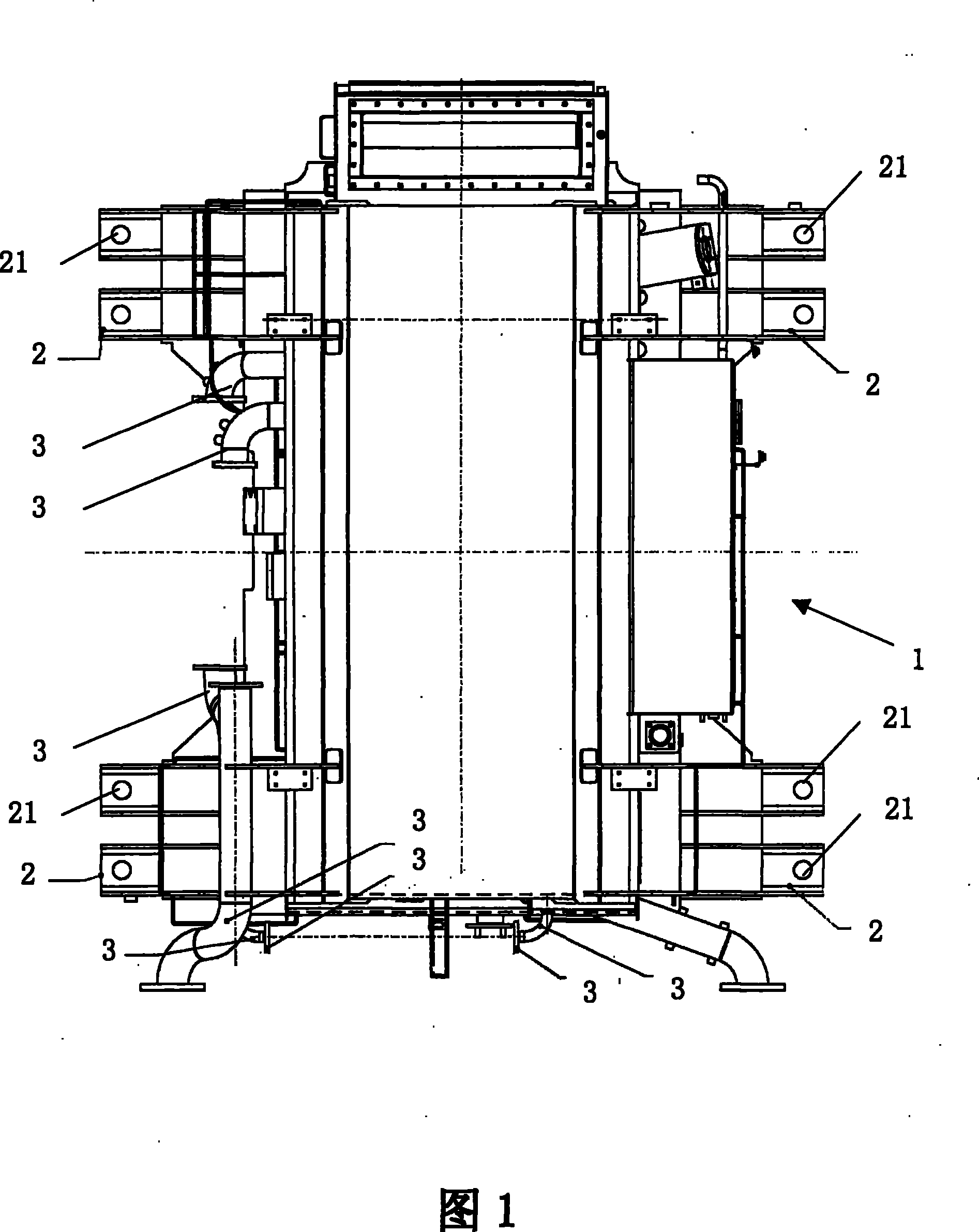
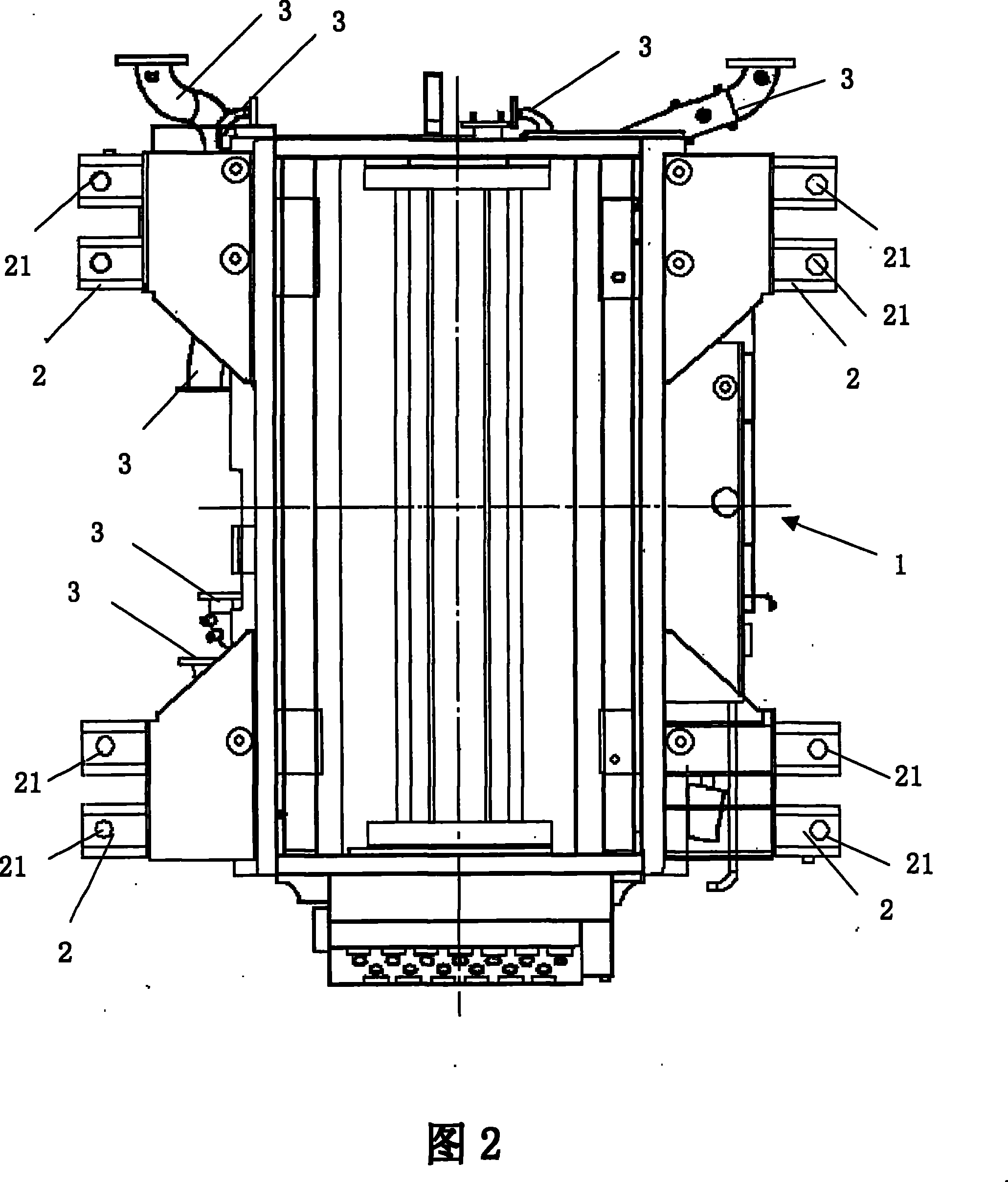
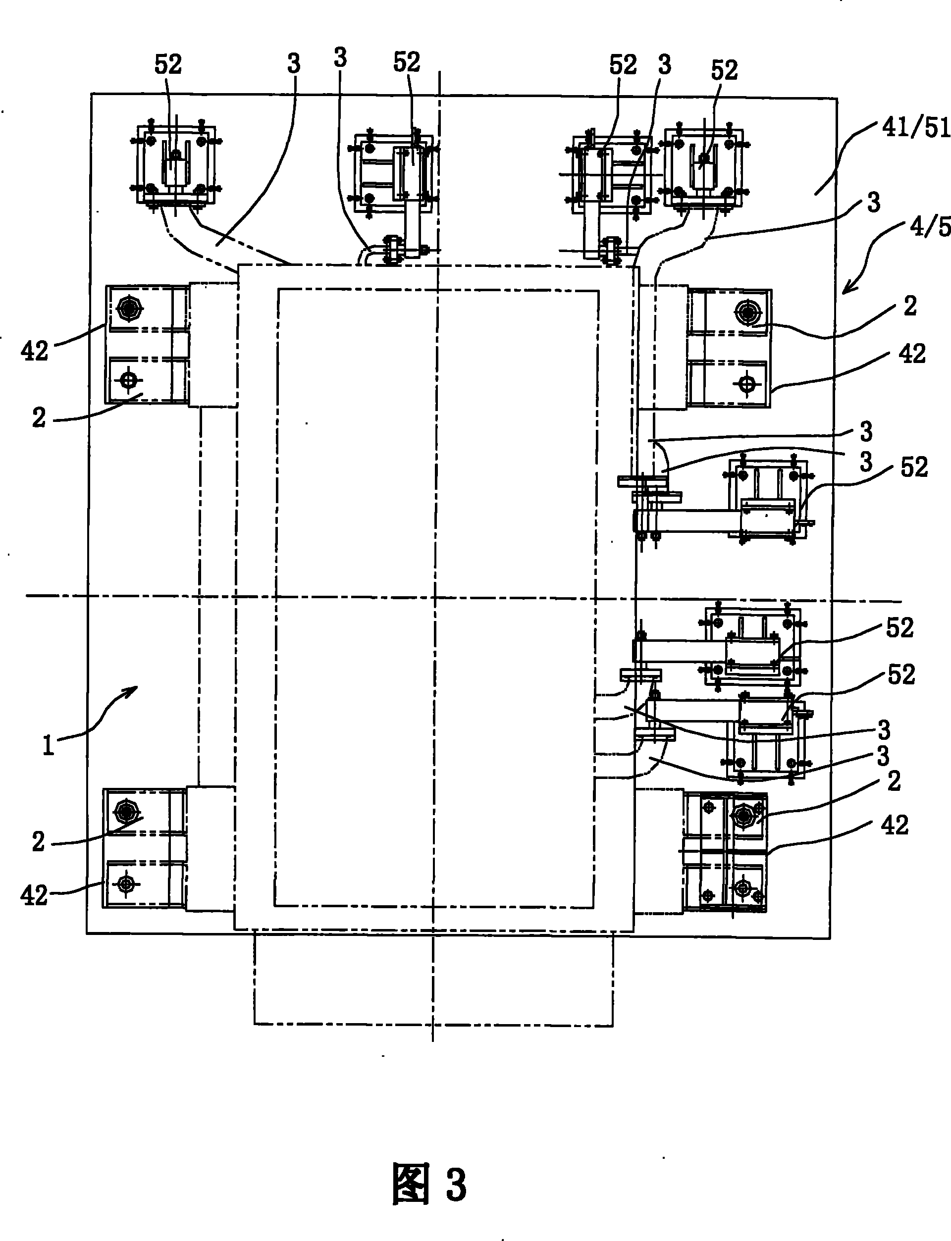
[0024] The invention provides a method for manufacturing a power-dispersed and power-concentrated transformer oil tank, referring to figure 1 , 2 As shown, the power dispersion and power concentration type transformer oil tank is an all-steel box structure, which includes a box body 1 and assembly accessories and non-assembly accessories arranged on the box body. Now the main transformer is pulled by an AWJ type locomotive The production process of the oil tank is taken as an example to specifically illustrate the manufacturing method of the present invention, and the manufacturing method may further comprise the steps:

[0025] A. Assembly welding box 1 and non-assembly accessories such as reinforcement plates, cable racks, and grounding seats;

[0026] B. Weld the assembly accessories such as the mounting base 2 and the 3 sets of oil pipes on the box body 1.

[0027] In the method of the present invention, the assembly accessories are welded at the end of the welding proce...


PUM


Abstract

The invention provides a manufacturing method for a power decentralization and centralization type transformer tank which comprises a tank body, assembly accessories and non-assembly accessories arranged on the tank body. The manufacturing method comprises the following steps: A, assembling and welding the tank body and the non-assembly accessories; and B, assembling and welding the assembly accessories on the tank body. Optimally, the assembly accessories comprise a mounting seat and an oil circuit connecting pipe; wherein, the mounting seat and the oil circuit connecting pipe are simultaneously welded in the end of the assembling and welding process. Accordingly, the invention minimizes the impact on the welding precision of the mounting seat, the oil circuit connecting pipe and other important assembly accessories caused by welding deformation and ensures the assembly and welding accuracy of the assembly accessories and the tank body so as to improve the passing rate of the products; besides, the invention can reduce the destressing adjustment and repair process after welding, shorten the working procedures and improve the production efficiency, and can easily achieve mass flowline production.

Description

technical field [0001] The present invention relates to a method for manufacturing a transformer oil tank for high-speed electric locomotives, in particular to a method for manufacturing a power-distributed and power-concentrated transformer oil tank installed on a power-distributed EMU and a power-concentrated electric locomotive. Background technique [0002] With the development of electrified railways in our country, higher and higher requirements are put forward for the electrical equipment of electric locomotives, and the continuous improvement of locomotive speed requires each component of the locomotive to be lighter and lighter. Therefore, the manufacturing of the transformer which accounts for 8-10% of the weight of the locomotive is very important, and the weight reduction of the transformer oil tank has also become a problem of great concern in the transformer industry. Two types of transformer oil tanks, power dispersion and power concentration, solve the above ...

Claims


Application Information

Patent Timeline
Patent Type & Authority Patents(China)
IPC IPC(8): H01F41/00H01F27/14
Inventor 李建萍马录宝武树安程春磊陈凤岐张海玉
Owner DATONG ELECTRIC LOCOMOTIVE OF NCR
Learn More