Water treatment system
A water treatment system and control system technology, applied in water/sewage treatment, water treatment parameter control, water/sewage treatment equipment, etc., can solve the problems of inconvenient use and inability to provide treated water as needed at any time
- Summary
- Abstract
- Description
- Claims
- Application Information
AI Technical Summary
Problems solved by technology
Method used
Image

Examples
example 1
[0025] Example 1. Experimental model
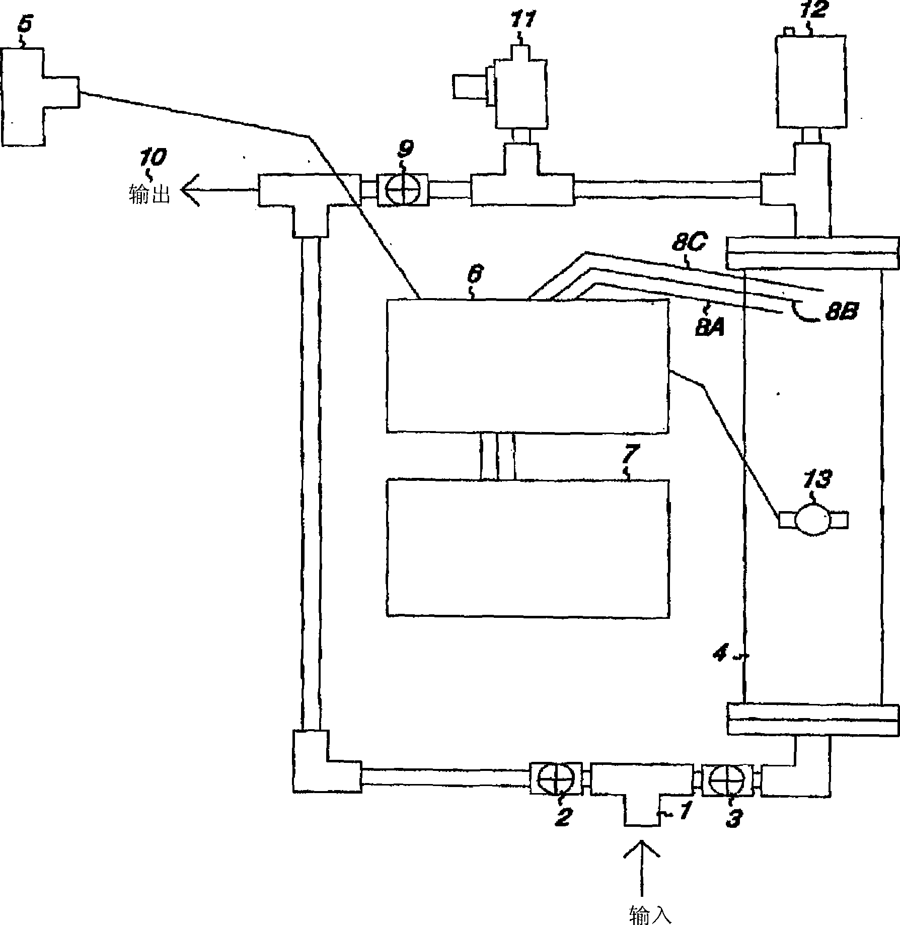
[0026] see figure 1 , Inlet 1 is attached to the water source to be treated. Valve 2 is closed; valve 3 is opened to allow water to flow into electrolysis chamber 4. When the flow switch 5 connected to the controller 6 senses water flow, the power supply 7 supplies voltage to the plates 8a, 8b and 8c, thereby forming oxygen. The oxidized water flows out through outlet 10 after passing through valve 9 . The water pressure reducing valve 11 and the gas pressure reducing valve 12 are used to reduce the pressure in the system. When the temperature sensor 13 senses an increase in temperature, the controller 6 deactivates the plates 8a, 8b and 8c.
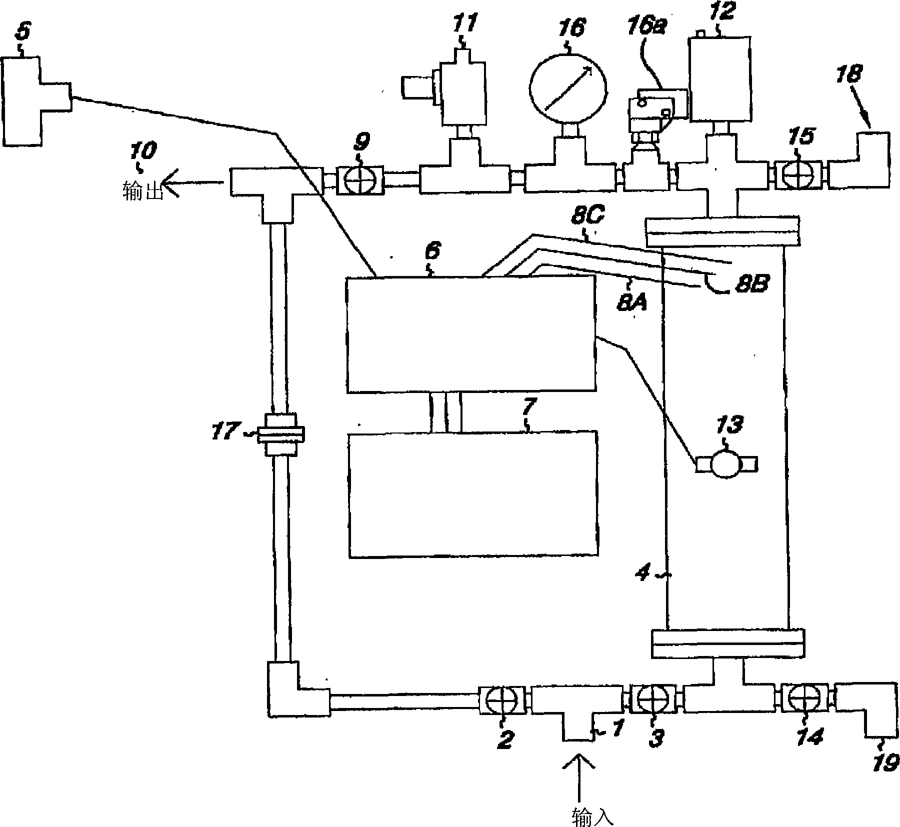
[0027] see figure 2 , Inlet 1 is attached to the water source to be treated. Valve 2 is closed; valve 3 is opened to allow water to flow into electrolysis chamber 4. Valves 14 and 15 are closed. When the flow switch 5 connected to the controller 6 senses water flow, the power supply 7 sup...
example 2
[0033] Example 2. Circuit Operation Instructions
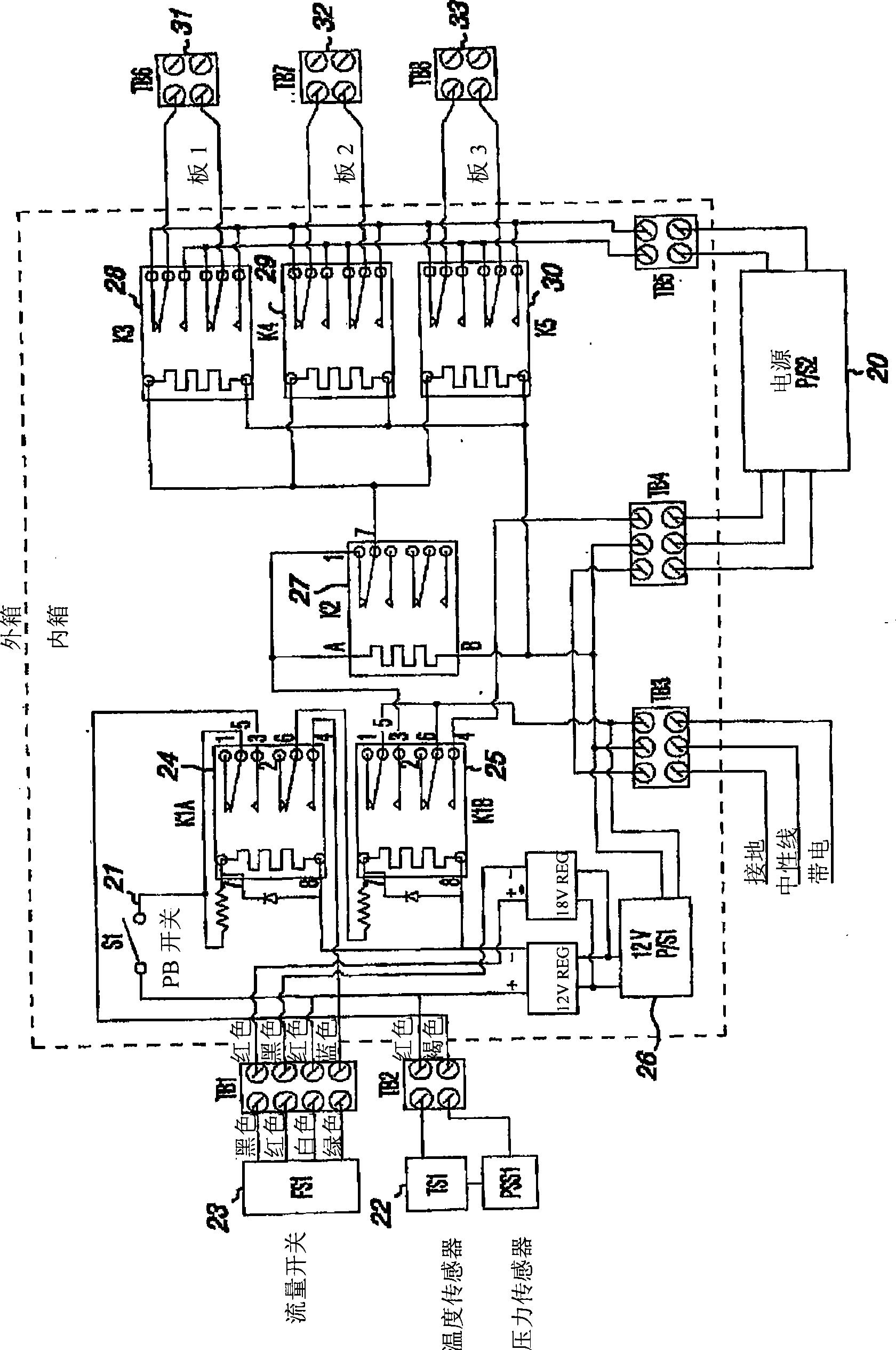
[0034] This illustration is based on an example system with three emitters that reverses the self-cleaning polarity each time the water flow is activated. Adjustable for larger or smaller systems. The circuit operation starts with applying a line voltage of 120V AC to the power supply 26, which converts the line voltage to 12V DC. The controller circuit is in electrical communication with the flow switch 23 , the temperature sensor 22 and the button switch 21 , and when the temperature sensor 22 indicates that the temperature is low, the button switch 21 activates the circuit, thereby applying 12V voltage to the button switch 21 . When the pushbutton switch is pressed, it energizes relay 24K1A. The relay is wired so that it remains energized after the button is released. The other contacts on this relay monitor the flow switch to detect if water is flowing. If so, the next relay 25K1B is energized, applying 120V AC volta...
example 3
[0037] Example 3. Transmitter configuration
[0038] Depending on the volume of fluid to be oxidized, the emitters of the present invention may be shaped in circular, rectangular, conical or other forms. One or more emitters may be disposed in a substrate, which may be metal, glass, plastic or other material. The base is not critical so long as the current is isolated from the electrodes by a non-conductive spacer material having a thickness of between 0.005 inches and 0.140 inches, preferably between 0.030 inches and 0.075 inches, most preferably is 0.065 inches. Within this distance, micron and nanoscale oxygen bubbles are formed. These bubbles are so small that they cannot escape and accumulate in the aqueous medium to form a so-called colloidal suspension of oxygen. Oxygen concentrations equal to 260% of the calculated saturation at the specified temperature and pressure have been obtained in static vessels. In straight-through devices, the oxygen suspension is enric...
PUM
| Property | Measurement | Unit |
|---|---|---|
| thickness | aaaaa | aaaaa |
Abstract
Description
Claims
Application Information
 - R&D
- Intellectual Property
- Life Sciences
- Materials
- Tech Scout
- Unparalleled Data Quality
- Higher Quality Content
- 60% Fewer Hallucinations
Browse by: Latest US Patents, China's latest patents, Technical Efficacy Thesaurus, Application Domain, Technology Topic, Popular Technical Reports.
© 2025 PatSnap. All rights reserved.Legal|Privacy policy|Modern Slavery Act Transparency Statement|Sitemap|About US| Contact US: help@patsnap.com