Supercharge Your Innovation With Domain-Expert AI Agents!

Method and device for producing optical fiber

A manufacturing method and optical fiber technology, applied in the direction of manufacturing tools, glass manufacturing equipment, fiber mechanical structure, etc., can solve the problem of not being able to control the thickness of the coating layer separately, and achieve the effect of high productivity

Active Publication Date: 2009-06-24
FURUKAWA ELECTRIC CO LTD
View PDF5 Cites 11 Cited by
  • Summary
  • Abstract
  • Description
  • Claims
  • Application Information

AI Technical Summary

Problems solved by technology

[0005] However, in the case of the double-coating method, since one coating die is used to form multiple resin layers, even if the outer diameter of the coated optical fiber is measured, only the total thickness of the coating layers can be calculated.
Therefore, there is a problem that the thickness of each coating layer cannot be individually controlled.

Method used


Image

  • Method and device for producing optical fiber
  • Method and device for producing optical fiber
  • Method and device for producing optical fiber

Examples


Embodiment approach 1

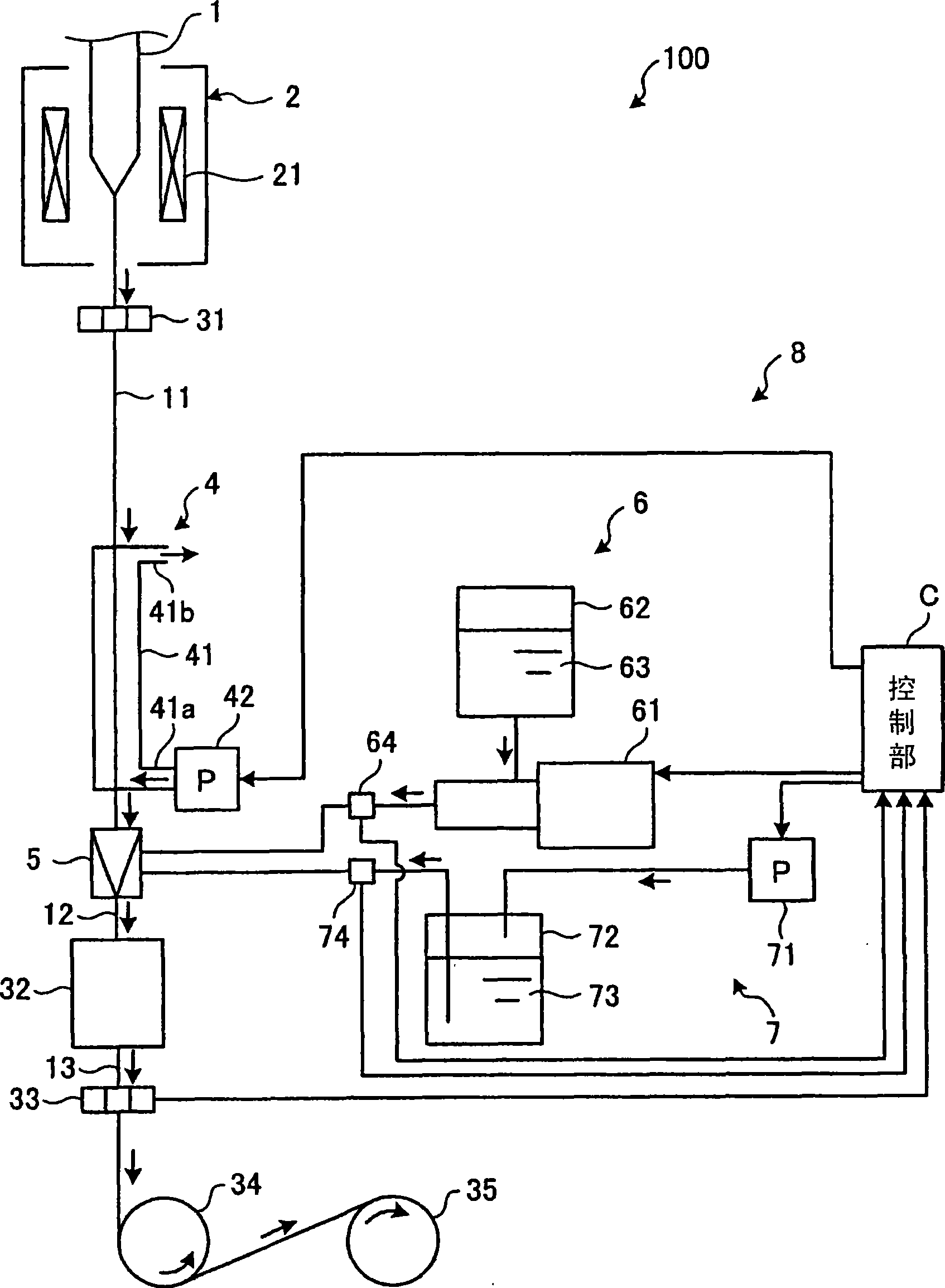
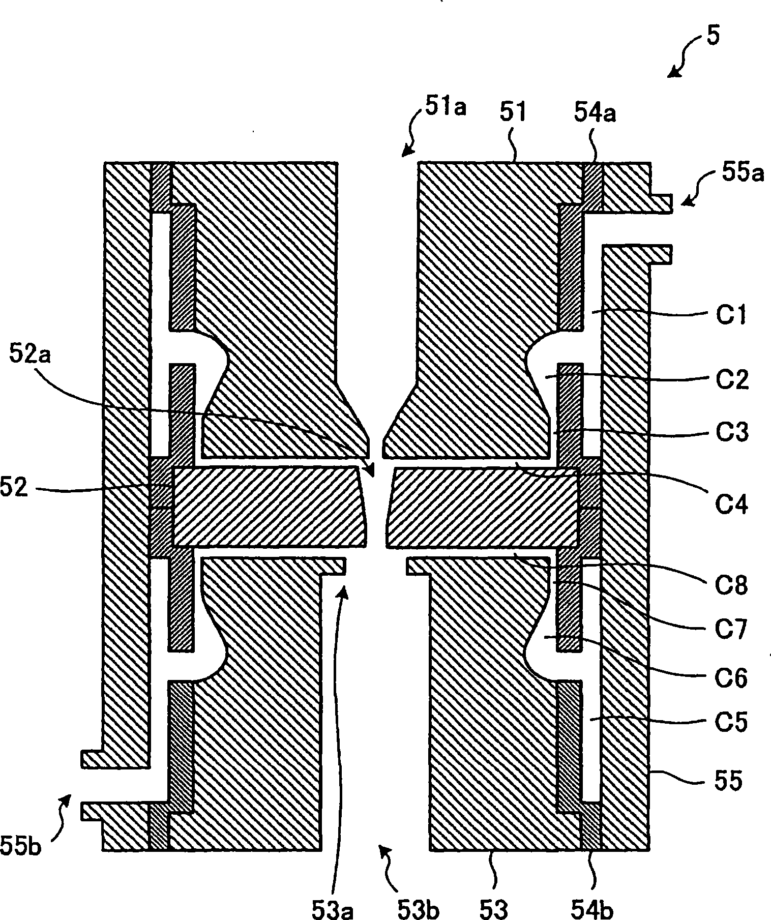
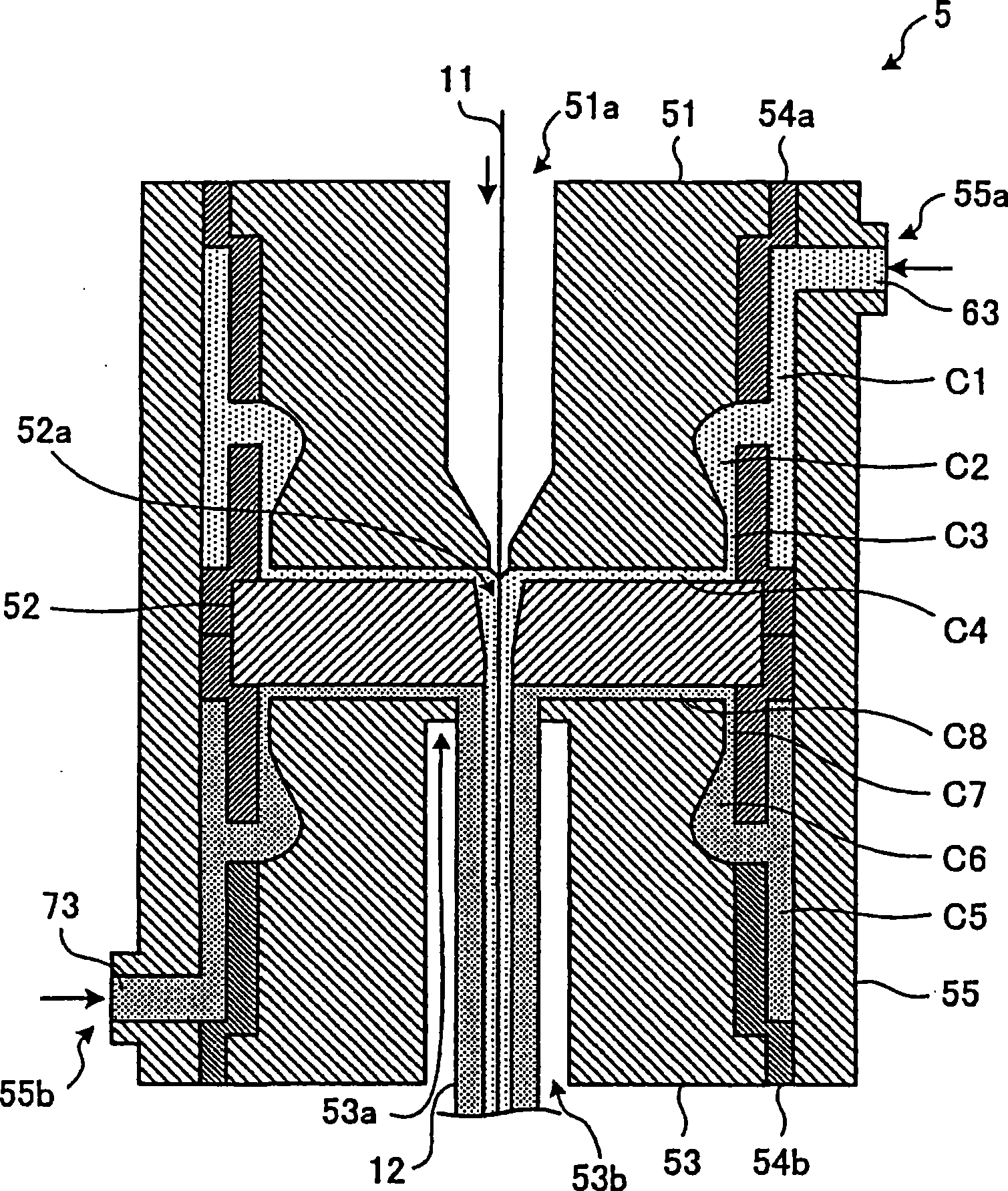
[0073] figure 1 It is a block diagram schematically showing the optical fiber manufacturing apparatus according to Embodiment 1 of the present invention. Such as figure 1 As shown, this manufacturing apparatus 100 has a wire drawing furnace 2, a temperature adjustment device 4, a resin coating device 8, and an ultraviolet irradiation device 32 as a coating layer forming device, and also includes laser outer diameter measuring devices 31, 32, guide rollers 34, and a winder 35 .

[0074] First, a method of manufacturing an optical fiber using the manufacturing apparatus 100 will be schematically described. In this manufacturing device 100, the drawing furnace 2 melts the front end portion of the optical fiber preform 1 by the heater 21 to draw the optical fiber 11, and then measures the outer diameter of the drawn optical fiber 11 by the laser outer diameter measuring device 31, and the temperature is adjusted. The device 4 cools the optical fiber 11 to a prescribed temperatu...

Embodiment 1

[0099] use as figure 1 The manufacturing apparatus shown manufactures an optical fiber according to the first embodiment. At this time, the linear speed of drawing is set to 2000 m / min, so that the outer diameter of the drawn optical fiber reaches 0.125 mm.

[0100] In addition, the number of revolutions of the quantitative pump is controlled so that the detection value of the pressure sensor reaches 1.2Mpa. At this time, the following control is carried out. When the outer diameter of the inner coating layer calculated according to the ejection amount is smaller than the target value of 0.19 mm, the flow rate of He gas in the temperature adjustment device is increased to reduce the temperature of the optical fiber, so that the rotation of the quantitative pump is reduced. When the number increases, when the situation is opposite, reduce the flow rate of He gas to increase the temperature of the optical fiber, so that the number of rotations of the quantitative pump is reduce...

Embodiment approach 2

[0107] Embodiment 2 of the present invention will be described below. In the optical fiber manufacturing method according to the second embodiment, in the same manufacturing apparatus 100 as in the first embodiment, the resin supply device 7 using a pressure pump is replaced with the same resin supply device as the resin supply device 6 using a quantitative pump. , to manufacture optical fibers with such a manufacturing device.

[0108] In the second embodiment, in the above-mentioned replaced resin supply device, the rotation speed of the metering pump is controlled in accordance with the outer diameter measured by the laser outer diameter measuring device 33 . According to Embodiment 2, as in Embodiment 1, even if the drawing speed of the optical fiber is high, the thickness of the inner coating layer, which cannot be directly measured, can be stabilized at a desired value in the longitudinal direction. The thickness of each layer of the two coating layers is stabilized at ...


PUM


Abstract

A process for producing an optical fiber, comprising the fiber drawing step of melting a distal end portion of optical fiber preform and carrying out optical fiber drawing; the resin layer coating step of causing the resultant optical fiber to pass through continuing multiple holes of a coating die so as to conduct resin coating in each of the multiple holes, thereby forming multiple resin layers on the outer circumference of the optical fiber; and the coating layer forming step of hardening the multiple resin layers into multiple coating layers, wherein in the resin layer coating step, while controlling the rate of output of a metering pumpso that the pressure of resin supply to at least the hole for forming of the innermost resin layer among the above multiple holes exhibits a given value, the resin is supplied to the coating die by means of the metering pump, and simultaneously the temperature of the optical fiber at the entry of the optical fiber in the coating die is controlled in conformity with any fluctuation of the rate of output of the metering pump so as to control the thickness of each of the coating layers, thereby realizing production of the optical fiber with its properties satisfactorily stabilized in the longitudinal direction thereof with high productivity.

Description

technical field [0001] The present invention relates to an optical fiber manufacturing method and an optical fiber manufacturing apparatus for forming a multilayer coating layer on the outer periphery of a drawn optical fiber. Background technique [0002] The process of manufacturing an optical fiber is to heat and melt an optical fiber base material made of glass and draw it, and then apply an ultraviolet curable resin with a coating mold to form a resin layer on the outer periphery of the drawn optical fiber, and then irradiate the resin layer with ultraviolet rays to make it cured to form a covering layer. The optical fiber coating is composed of multiple layers of resins with different properties to give the optical fiber the necessary strength and various other characteristics. [0003] Here, in order to impart required characteristics to the optical fiber by the coating layers, the thickness of each coating layer must be a predetermined value. For this reason, in th...

Claims


Application Information

Patent Timeline
Patent Type & Authority Applications(China)
IPC IPC(8): G02B6/44
CPCC03B37/02718C03C25/18
Inventor 折田伸昭彼得·哈斯洛夫弗莱明·彼得森
Owner FURUKAWA ELECTRIC CO LTD
Features
  • R&D
  • Intellectual Property
  • Life Sciences
  • Materials
  • Tech Scout
  • Unparalleled Data Quality
  • Higher Quality Content
  • 60% Fewer Hallucinations
Learn More