Ultrasonic diagnostic apparatus, ultrasonic image processing apparatus, and ultrasonic image processing method
A diagnostic device and image processing technology, applied in echo tomography, organ movement/change detection, etc., can solve the problems of no specific proposal, unfavorable high-speed processing, etc.
- Summary
- Abstract
- Description
- Claims
- Application Information
AI Technical Summary
Problems solved by technology
Method used
Image
Examples
Embodiment 1
[0021] Hereinafter, embodiments of the present invention will be described with reference to the drawings. In addition, in the following description, the same code|symbol is attached|subjected to the structural element which has substantially the same function and structure, and it repeats description only when necessary.
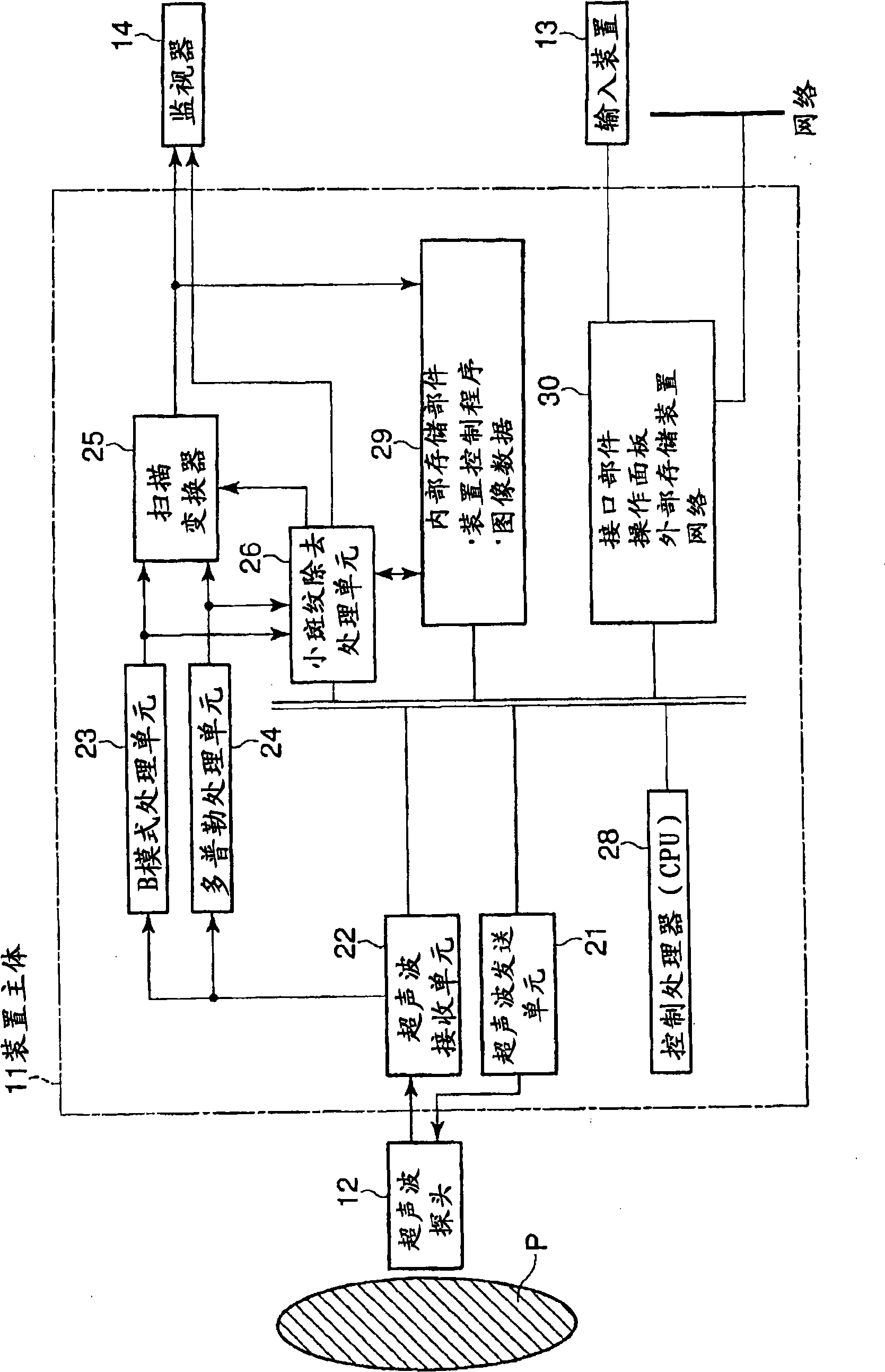
[0022] figure 1 A block configuration diagram of the ultrasonic diagnostic apparatus 1 of the present embodiment is shown. As shown in the figure, this ultrasonic diagnostic apparatus 1 includes an ultrasonic probe 12, an input device 13, a monitor 14, an ultrasonic transmitting unit 21, an ultrasonic receiving unit 22, a B-mode processing unit 23, a Doppler processing unit 24, a scan conversion 25, a small speckle removal processing unit 26, a control processor (CPU) 28, an internal storage unit 29, and an interface unit 30. Hereinafter, the function of each component will be described.
[0023] The ultrasonic probe 12 has: a plurality of piezoelectric ...
Embodiment 2
[0070] In Embodiment 1, an example of performing small speckle removal processing on two-dimensional image data (raw data) was shown. On the other hand, a case where the ultrasonic diagnostic apparatus 1 of this embodiment executes small speckle removal processing on three-dimensional volume data (raw data) will be described.
[0071] Figure 4 It is a diagram showing the configuration of the ultrasonic diagnostic apparatus 1 of the present embodiment. in with figure 1 In the case of comparison, there are differences in the following points: a volume data generation unit 31 is also provided; and the small speckle removal processing unit 26 performs small speckle removal processing on volume data from the volume data generation unit 31 .
[0072] The volume data generation unit 31 generates B-mode volume data using the B-mode image data received from the B-mode processing unit 23 . Also, the volume data generation unit 31 generates Doppler mode image volume data using the Do...
Embodiment 3
[0079] As described above, Embodiment 2 shows an example in which the present invention is applied to 3D volume data before 3D image processing, but thereafter, as Embodiment 3, an example in which the present invention is applied to 3D display after 3D image processing is shown. .
[0080] In Embodiment 2, an example of performing small speckle removal processing on B-mode volume data before 3D image processing is shown. On the other hand, a description will be given of a case where the ultrasonic diagnostic apparatus 1 of this embodiment executes small speckle removal processing on image data after three-dimensional image processing.
[0081] Figure 6 It is a diagram showing the configuration of the ultrasonic diagnostic apparatus 1 of the present embodiment. in with Figure 4 In the case of comparison, there are differences in the following points: a volume data generation unit 31 is also provided;
[0082] Figure 7 It is a diagram showing an example of a format in w...
PUM
 Abstract
Description
Claims
Application Information
 - R&D
- Intellectual Property
- Life Sciences
- Materials
- Tech Scout
- Unparalleled Data Quality
- Higher Quality Content
- 60% Fewer Hallucinations
Browse by: Latest US Patents, China's latest patents, Technical Efficacy Thesaurus, Application Domain, Technology Topic, Popular Technical Reports.
© 2025 PatSnap. All rights reserved.Legal|Privacy policy|Modern Slavery Act Transparency Statement|Sitemap|About US| Contact US: help@patsnap.com


