Optical sensor for high-flux dust particle counter

A particle counter and optical sensor technology, applied in the field of optical sensors, can solve problems such as low light energy conversion efficiency, difficult system adjustment, unfavorable signal-to-noise ratio, etc., and achieve the effects of reducing transmission loss, improving signal-to-noise ratio, and high power density

Inactive Publication Date: 2009-07-01
NANJING UNIV OF SCI & TECH
View PDF1 Cites 22 Cited by
  • Summary
  • Abstract
  • Description
  • Claims
  • Application Information

AI Technical Summary

Problems solved by technology

The problems existing in the prior art are: 1. The light source adopts halogen tungsten lamp, which generates a large amount of heat, is not a monochromatic light source, and has low light energy conversion efficiency; 2. Multiple lens combinations are set in the illumination light path and the scattered light collection light path, and the light path is very complicated. , the loss of light energy is relatively large; 3. The retroreflector is used to make the system generate two opposite lighting beams, and quasi-symmetric lighting is used for the sampling airflow. Although it can increase the light energy of the photosensitive area and improve the measurement range, it makes the system adjust Difficult, stray light increases, which is not conducive to the improvement of signal-to-noise ratio

Method used


Image

  • Optical sensor for high-flux dust particle counter
  • Optical sensor for high-flux dust particle counter
  • Optical sensor for high-flux dust particle counter

Examples


Embodiment Construction

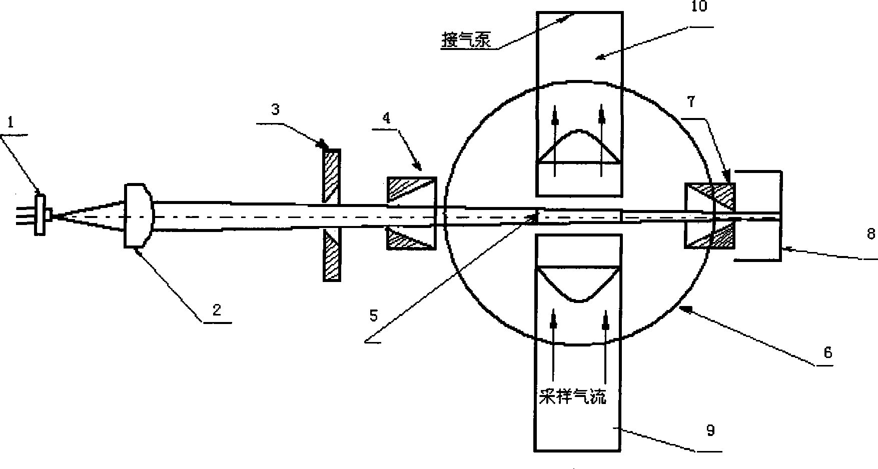
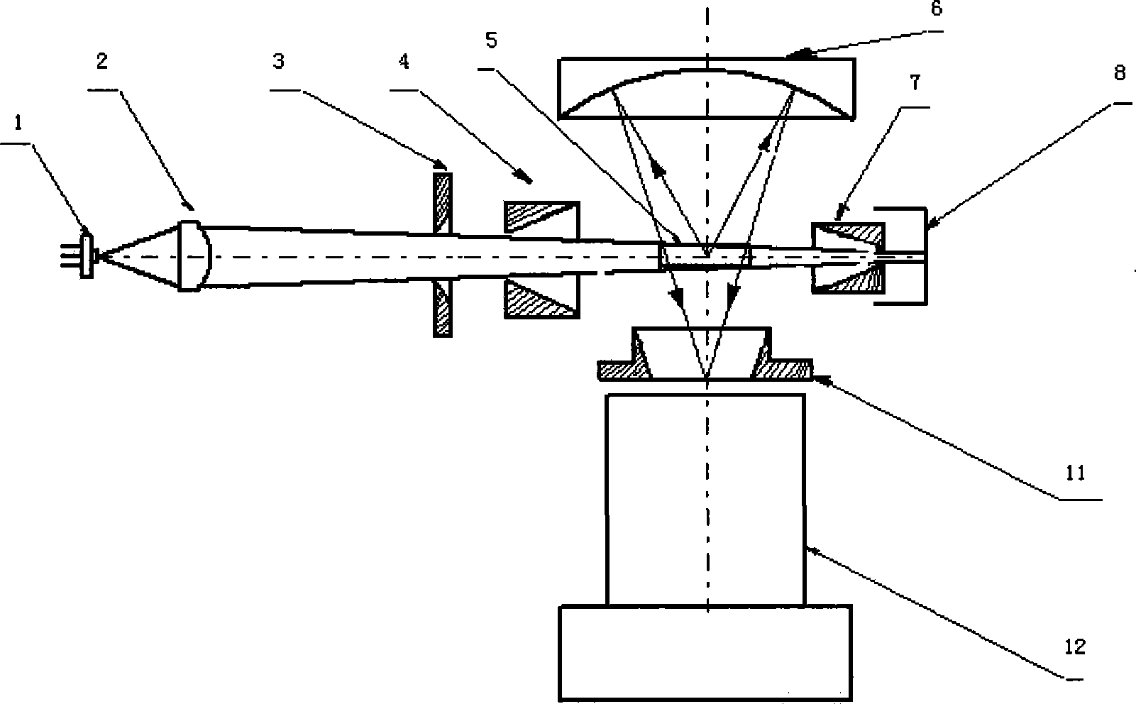
[0009] combine figure 1 , figure 2 , The optical sensor of the large-flow dust particle counter of the present invention is a right-angle scattering optical system, including an illumination system, a scattered light collection system, and an air path system. The lighting system consists of a semiconductor laser 1, an aspheric mirror 2, a first incident aperture 3, a second incident aperture 4, an exit aperture 7, and an optical trap 8. The power of the semiconductor laser 1 is 5mW and the wavelength is 650nm. The focal length aspheric mirror 2 focuses two-dimensionally, and the converging point is behind the photosensitive area, so as to ensure the uniform light intensity of the photosensitive area 5 along the axial direction, and the width of the light beam at the photosensitive area 5 is twice the width of the gas nozzle 9 . The laser beam enters the optical trap 8 after passing through the photosensitive area 5 and is absorbed by the optical trap 8 . Among them, the ape...


PUM


Abstract

The invention relates to an optical sensor of large flux dust particle counter, comprising a laser source, wherein the light path of the laser source is provided with an aspheric lens, an indicant stop, an outgoing stop and a light trap in turn; a light path surface mirror, field stop and a photoelectric detector are arranged between the incident stop and the outgoing stop and vertical to the light path; a light sensitive zone and the light sensitive surface of the photoelectric detector are respectively arranged at two sides of the spherical center of the spherical mirror; the rectangle field stop is arranged at the front of the photoelectric detector and fit with the shape of the light sensitive zone. The illumination light path and scattered light collection light path of the optical sensor have simple design and easy adjustment. A stop is arranged at the front of the light sensitive zone to reduce the scattered light entering into the chamber, and a stop is arranged between the light sensitive zone and the light trap to prevent the light beam entering into the light trap from being reflected back to the chamber, thereby improving the signal noise ratio of the sensor. The field stop adopts a horn mouth type obscuration stop for preventing scattered light on the light path from directly entering into the detector.

Description

technical field [0001] The invention relates to a cleanliness detection device, in particular to an optical sensor for a large-flow dust particle counter. Background technique [0002] In the prior art, the technical scheme adopted by the optical sensor of the laser dust particle counter, such as the utility model patent "optical sensor of the laser dust particle counter" applied by Huang Huijie and others at the Shanghai Institute of Optics and Fine Mechanics of the Chinese Academy of Sciences on March 6, 2002 "(Patent No. CN2480832Y), which adopts a right-angle scattering optical system structure, the optical axis of the illumination optical system, the axis of the scattered light collection system and the axis of the gas system intersect perpendicularly in the center of the photosensitive area, and the illumination optical system uses a halogen lamp , in the forward direction of the light beam emitted by the light source, an illumination lens group and a first spherical r...

Claims


Application Information

Patent Timeline
Patent Type & Authority Applications(China)
IPC IPC(8): G01N15/14G01N21/17
Inventor 卞保民彭刚王春勇贺安之
Owner NANJING UNIV OF SCI & TECH
Why Eureka
Try Eureka