Single-phase power clock trigger based on electric charge resumption

A single-phase power and flip-flop technology, which is applied to logic circuits, electrical components, and electric pulse generation, can solve problems such as little practical value, complex circuit structure, and few sequential logic unit structures.

Inactive Publication Date: 2009-07-01
INST OF MICROELECTRONICS CHINESE ACAD OF SCI
View PDF0 Cites 12 Cited by
  • Summary
  • Abstract
  • Description
  • Claims
  • Application Information

AI Technical Summary

Problems solved by technology

The characteristic of the former is that the power consumption of the circuit can be reduced to zero in theory, but the circuit must use reversible logic to complete the function of the circuit. At the same time, it needs more pulse power supply. The circuit structure is complex and the operating frequency is low. It is very difficult to realize, so it is practical The value is not much; compared with the former, the latter has a simple circuit structure, no limitation of reversible logic, and the circuit requires less pulse power, so it is easier to apply
The disadvantage of semi-adiabatic circuits is that the recovery efficiency is not as high as that of fully adiabatic circuits
[0018] Due to the huge application value of semi-adiabatic circuits, the research on semi-adiabatic circuits has been very active in the world in recent years, and many new types of semi-adiabatic circuits have emerged, but most of them are combinational logic units, and the structure of sequential logic units is still relatively small.

Method used


Image

  • Single-phase power clock trigger based on electric charge resumption
  • Single-phase power clock trigger based on electric charge resumption
  • Single-phase power clock trigger based on electric charge resumption

Examples


Embodiment Construction

[0056] In order to make the object, technical solution and advantages of the present invention clearer, the present invention will be described in further detail below in conjunction with specific embodiments and with reference to the accompanying drawings.

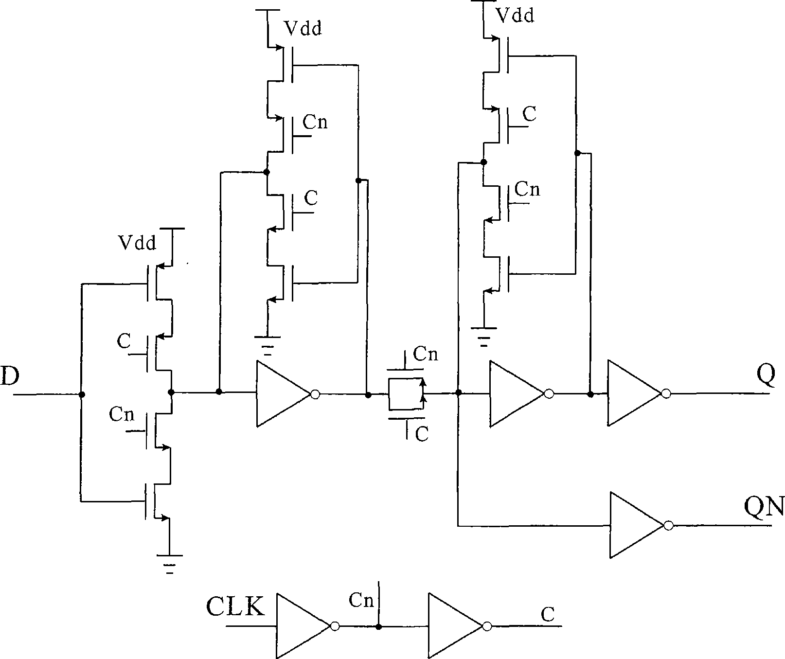
[0057] see Figure 6As shown, the circuit structure of a single-phase power clock flip-flop based on charge recovery in the present invention includes three parts of an RS flip-flop composed of an input inverter, a charge recovery unit and a NOR gate. The function of the input inverter is to generate two inverted signals and send them to the charge recovery unit to control the on-off of the Mn1 tube and the Mn2 tube; the charge recovery unit adopts semi-adiabatic circuit technology and uses the power clock Pclk to recover the charge to achieve The purpose of reducing the power consumption of the circuit; the RS flip-flop latches the output of the charge recovery unit to generate the correct output.

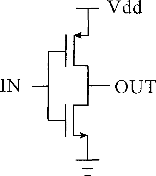
[0058] input inverte...


PUM


Abstract

The invention relates to a single-phase power clock trigger based on charge recovering. The trigger comprises an input inverter used for generating two inverse signals and sending the two signals to a charge recovery unit, a cross-coupling charge recovery unit used for reducing the power consumption of a circuit, and a RS trigger used for latching the output of a charge recycling unit, wherein, the input and the output of the inverter are connected with two input terminals of the cross-coupling charge recovery unit respectively; and two output terminals of the cross-coupling charge recovery unit are connected with two input terminals of the RS trigger. The trigger adopts the single phase power clock (similar to a sine wave power) Pclk to complete the function of the trigger D, input and output signals adopt the square wave and can be directly cascaded with a traditional CMOS logic circuit to complete the logic. Compared with a traditional trigger, the trigger of the invention has the advantages that the power consumption is low, and the extremely low power consumption can be realized particularly when the data change rate is low; the number of transistors is small; and the single-phase clock is adopted.

Description

technical field [0001] The invention belongs to the technical field of low-power integrated circuit design, is a charge recovery logic sequential circuit, and in particular relates to a single-phase power clock trigger based on charge recovery. Although it is based on charge recovery logic, it can be directly cascaded with traditional CMOS logic circuits to complete the logic. Background technique [0002] Charge recovery technology, also known as energy recovery or adiabatic circuit technology, is a low-power circuit technology that has emerged in the past ten years. Using this technology can significantly reduce the power consumption of the circuit, and has become a low-power circuit technology. It is a hot spot in the research field of power consumption integrated circuit technology. Using this technology, the power consumption can be reduced to zero in theory, so this technology was originally called adiabatic circuit technology. [0003] To illustrate the advantages o...

Claims


Application Information

Patent Timeline
Patent Type & Authority Applications(China)
IPC IPC(8): H03K3/037H03K19/20H03K19/0948
Inventor 高雷声刘海南周玉梅
Owner INST OF MICROELECTRONICS CHINESE ACAD OF SCI
Why Eureka
Try Eureka