Macro/micro drive accurate feeding system with parallel series guiding rail joint portion

A feed system, macro and micro drive technology, applied in the direction of manufacturing tools, metal processing machinery parts, metal processing equipment, etc., can solve the problems of motion accuracy impact, damage, and bad actuator stress conditions, etc., to achieve load bearing capacity Strong, high motion precision, high guiding precision effect

Inactive Publication Date: 2009-07-08
XIAN UNIV OF TECH
View PDF0 Cites 14 Cited by
  • Summary
  • Abstract
  • Description
  • Claims
  • Application Information

AI Technical Summary

Problems solved by technology

For the above situation, if the micro-movement slide table uses a two-dimensional planar flexible hinge mechanism to determine its relative pose of the macro-motion slide table, the micro-motion slide table cannot bear large loads or full loads; the guiding accuracy cannot be guaranteed; it is used for micro-drive actuation The force condition of the actuator is bad (because the actuator can bear a large thrust, but it is best not to bear or only bear a slight lateral force and moment), which will affect the working performance of the actuator and even cause damage; the motion accuracy will also be affected

Method used


Image

  • Macro/micro drive accurate feeding system with parallel series guiding rail joint portion
  • Macro/micro drive accurate feeding system with parallel series guiding rail joint portion
  • Macro/micro drive accurate feeding system with parallel series guiding rail joint portion

Examples


Embodiment Construction

[0023] The present invention will be described in detail below in conjunction with the accompanying drawings and specific embodiments.

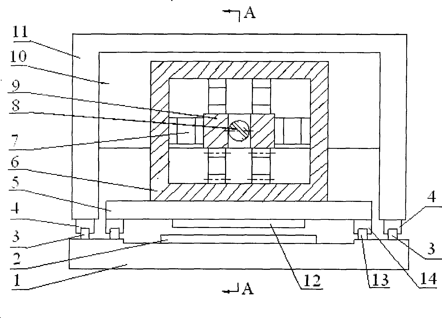
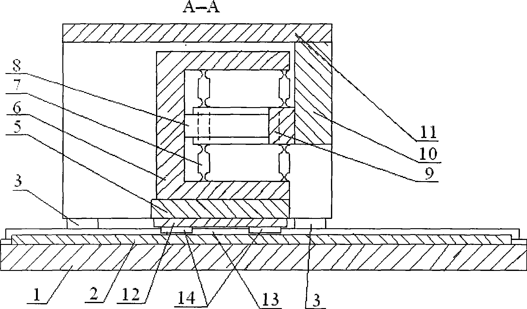
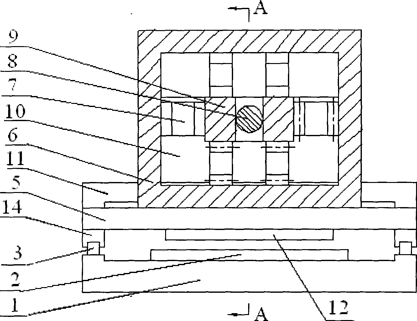
[0024] The structure of an embodiment of the precision feed system of the present invention, such as figure 1a, 1b shown. Including the slide seat 1, the upper surface of the slide seat 1 is fixedly installed with the primary 2 of the linear motor, the two sides of the primary 2 of the linear motor are symmetrically provided with the fixed rail 3 of the movement guide rail of the micro-motion slide table, and the movement guide rails of the two micro-motion slide table The moving rails 4 of the motion guide rails of the micro-motion slide table are respectively arranged on the top of the fixed rails 3. The moving rails 4 of the motion guide rails of the micro-motion slide table can move along the fixed rail 3 of the motion guide rails of the micro-motion slide table. The moving rail 4 is fixedly connected with the micro-moving slide table 11...


PUM


Abstract

The present invention discloses a macro micro-drive precise feed system which is provided with a parallel connection slide way combination part. The macro micro-drive precise feed system comprises a slide carriage, a primary electrode of linear electric motor, a secondary electrode of linear electric motor, a macro-motion slide platform and a hollow actuator deformation slide way supporting component which is provided with an opening at one edge, wherein the slide carriage, the primary electrode, the second electrode, the macro-motion slide platform and the hollow actuator deformation slide way supporting component are installed in turn from the lower part to the upper part. A macro-motion slide platform motion guide way is installed between the slide carriage and the macro-motion slide platform in parallel. An actuator deformation flexible hinge assembly and a piezoelectric actuator are installed in the actuator deformation slide way supporting component. The actuator deformation slide way supporting component is fixedly connected with one end of an actuator deformation slide way micro motion block. The other end of actuator deformation slide way micro motion block extends out from the opening of actuator deformation slide way supporting component and is fixedly connected with a connector which is fixedly connected with a micro motion slide platform. The macro micro-drive precise feed system of the invention has the characteristics of high feed precision, high guiding precision, strong bearing capacity and excellent force applying state of actuator. The invention can be used for the middle-large scale multi-axis synchronous precise and ultra-precise numerical control machine tool, and can also be used for other precise digital control machine.

Description

technical field [0001] The invention belongs to the technical field of precision numerical control machine tools, and relates to a feed system for precision and ultra-precision numerical control machine tools suitable for large-scale, full-load, and three-dimensional complex surface processing, and in particular to a macro-micro machine tool with a hybrid guide rail junction. Drive precision feed system. Background technique [0002] With the development of science and technology, there are more and more processing requirements for large-scale, three-dimensional complex contours, and high-precision parts. High-speed, high-precision high-performance CNC machine tools for processing. All countries are competing to research and develop large-scale precision five-axis processing machine tools and coordinate-level precision processing machine tools. [0003] The machine tool feed system is one of the key factors affecting the overall performance of the machine tool. Drive, tra...

Claims


Application Information

Patent Timeline
Patent Type & Authority Applications(China)
IPC IPC(8): B23Q5/22B23Q5/28
Inventor 黄玉美刘定强李虎杨新刚武宏璋谢礼
Owner XIAN UNIV OF TECH
Why Eureka
Try Eureka