Rotating servo oil motor

A servo oil and motor technology, applied in fluid pressure actuators, engine components, machines/engines, etc., can solve problems such as large shaft diameter, unstable turbine load control, and slow transmission mechanism

Active Publication Date: 2009-07-08
QINGDAO JIENENG STEAM TURBINE GROUP CO LTD
View PDF0 Cites 3 Cited by
  • Summary
  • Abstract
  • Description
  • Claims
  • Application Information

AI Technical Summary

Problems solved by technology

[0003] In view of this, the present invention is to provide a rotary servo oil motor to solve the above-mentioned rotary disc valve with a large diameter of the rotating shaft, and there is an interlocking gap between the gear and the rack, so that the transmission mechanism is slow and the turbine load control is unstable.

Method used


Image

  • Rotating servo oil motor
  • Rotating servo oil motor

Examples


Embodiment Construction

[0012] In order to clearly illustrate the technical solutions in the present invention, preferred embodiments are given below and detailed descriptions are given in conjunction with the accompanying drawings.

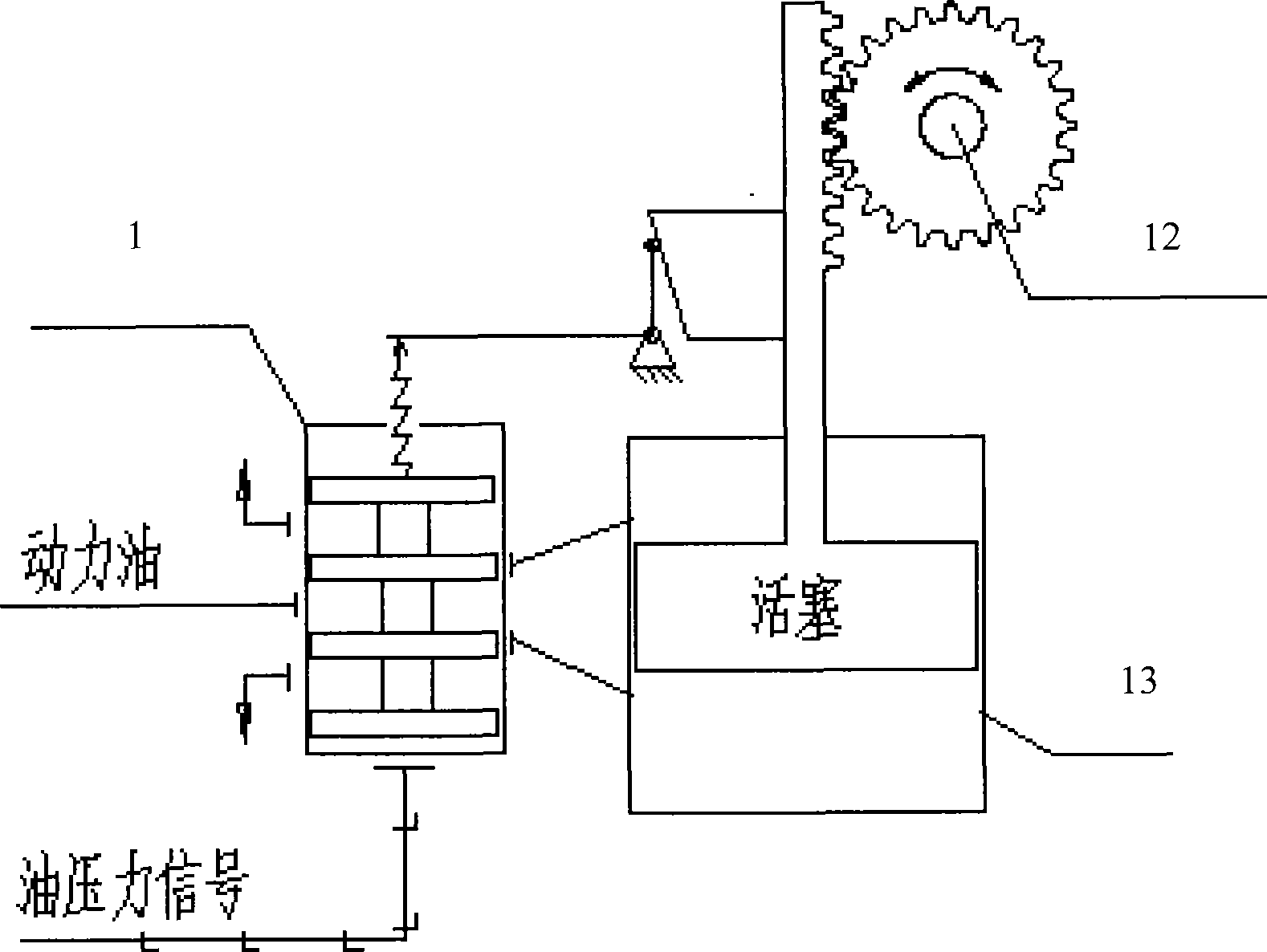
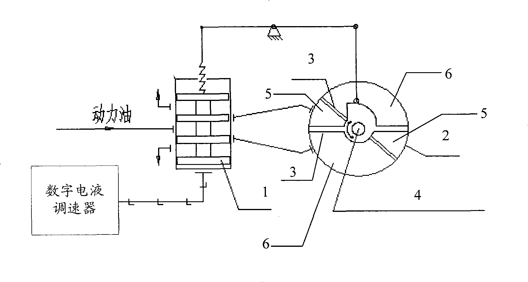
[0013] see figure 1 , the rotary servo oil motor includes: the oil valve 1 receiving the power oil is connected to the digital electro-hydraulic governor that generates the control signal, the oil valve 1 inputs the power oil into the corresponding chambers in the connected oil cylinder 2 according to the control signal, and drives The cam and the rotating flap connected to the rotating shaft 4 in the oil cylinder 2 rotate, and the rotating flap rotates to adjust the air valve to control the speed and load of the turbine.

[0014] The DEH control signal generated by the digital electro-hydraulic governor enters the bottom of the slide valve 1, pushing the slide valve 1 to move up or down, and the power oil with high pressure and large flow enters the chamber 5 or chambe...


PUM


Abstract

The invention discloses a rotary servo oil motor. An oil valve for receiving power oil is connected with a digital electro-hydraulic governor which generates control signals; the oil valve inputs the power oil to corresponding cavities connected in an oil cylinder according to the control signals so as to drive a cam and a rotary valve which are connected with a rotating shaft in the oil cylinder to rotate; the rotary valve drives an adjusting air valve which controls the rotating speed of a steam turbine; and the cam on the rotating shaft is further connected with a restorer which adjusts a slide valve to return to a balance position according to the rotational angle value of the rotating shaft. The rotary servo oil motor performs rotary motion to drive a butterfly adjusting valve to rotate directly without generating additional driving friction force. A servo oil motor shaft can be in rigid connection with a butterfly valve shaft without underdrive. The rotary servo oil motor can reduce the rotating shaft diameter of a rotary butterfly valve so that the drive of a driving mechanism is quick, and the load control of the steam turbine is stable.

Description

technical field [0001] The present invention relates to motors, in particular to rotary servo oil motors. Background technique [0002] Among the currently used steam turbine steam distribution mechanisms, the servo oil motor only performs linear motion, such as figure 1 As shown, if the disc valve 12 for rotary motion is controlled, the spool valve 1 switches the oil circuit under the control signal of the oil circuit, and the piston in the oil cylinder 13 of the servo oil motor is controlled by the power oil to produce a linear motion, and is converted through the gear and the rack. When the disc valve 12 rotates, a large pulling force is generated between the piston and the disc valve shaft, resulting in a large unfavorable additional friction force, which makes the diameter of the servo oil motor piston large, and also makes the rotating disc The diameter of the shaft of the valve is large, resulting in a high cost of the servo mechanism; in addition, there is an interl...

Claims


Application Information

Patent Timeline
Patent Type & Authority Applications(China)
IPC IPC(8): F15B15/02F15B21/02F01D17/00
Inventor 董京宗郑晓宗胡建国陈进
Owner QINGDAO JIENENG STEAM TURBINE GROUP CO LTD
Why Eureka
Try Eureka