
Hollow coupling reactor

A technology of coupled reactance and hollow core, applied in the direction of inductors, fixed inductors, circuits, etc., can solve the problems of small leakage reactance, small coupling coefficient, and high coupling degree of reactors, and achieve small leakage reactance, good linearity, and coupling degree high effect

Inactive Publication Date: 2009-07-08
HUAZHONG UNIV OF SCI & TECH +1
View PDF0 Cites 20 Cited by
  • Summary
  • Abstract
  • Description
  • Claims
  • Application Information

AI Technical Summary

Problems solved by technology

[0004] The air-core coupling reactor provided by the present invention solves the problem of small coupling coefficient of the existing air-core coupling reactor, realizes high coupling degree between each phase and each arm of the reactor, and small leakage reactance

Method used


Image

  • Hollow coupling reactor
  • Hollow coupling reactor
  • Hollow coupling reactor

Examples


Embodiment Construction

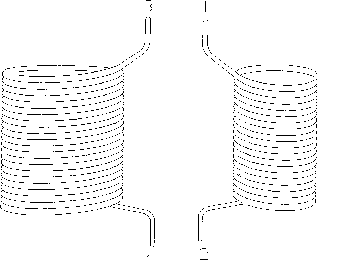
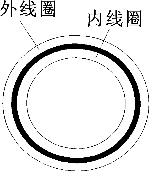
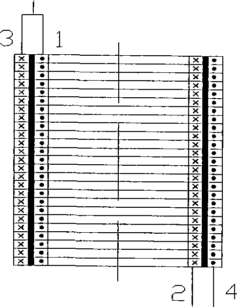
[0030] As shown in FIG. 1(A), the coupling coil of the present invention is composed of an inner coil and an outer coil, and the wires of the inner and outer coils are wound in opposite directions and wound into a hollow coaxial cylinder. The inner coil input terminal 1, the inner coil output terminal 2, the outer coil input terminal 3, and the outer coil output terminal 4. Each coil has only a single-layer winding, and the split winding method is not used.

[0031] As shown in Figure 1(B), 1-2 and 3-4 are two coils coupled to each other, the inner and outer coils are wound radially, and the winding directions of the two coils are opposite, as shown in Figure 1( In A), the inner coil 1-2 is wound clockwise, and the outer coil 3-4 is wound counterclockwise. The inter-turn insulation of the coil and the insulation withstand voltage level of the interlayer insulation are determined according to the voltage level of the system where the coil is located; in order to reduce the requ...


PUM


Abstract

A hollow mutual reactor belongs to reactor devices, and solves the problem that a coupling coefficient of the prior hollow mutual reactor is small. The invention provides a first form comprising mutually independent three-phase reactors, wherein, each phase reactor consists of coupling coils, a patching panel and a supporting insulator; the coupling coils consist of an inside coil and an outside coil with leads in opposite winding directions; a hollow coaxial cylinder is formed by winding; the outside coil winds outside the inside coil; and the inter-turn and the interlayer of the inside and the outside coils are all insulated. The invention further provides a second form comprising mutually independent three-phase reactors, wherein, each phase reactor consists of coupling coils, a patching panel and a supporting insulator. In each phase reactor, two or more coupling coils with different inside diameters are nested in turn with each other from inside to outside to form nesting coils, and the layers of the coupling coils are insulated and have air gaps for heat dissipation. The hollow mutual reactor has the advantages of low noise, good linearity, high mechanical strength, great stability margin, high coupling degree between arms of the mutual reactor, and small leakage reactance.

Description

technical field [0001] The invention belongs to a reactor device, in particular to a tightly coupled air-core coupled reactor. Background technique [0002] With the continuous strengthening of power system networking, the short-circuit capacity of the system is getting larger and larger, exceeding the breaking capacity of the circuit breaker. Fault current limiting interruption is an option. Traditional current-limiting reactors are connected in series in the power system. Even when the power system is working normally, the reactor shows a large impedance, which greatly reduces the transmission capacity and stability of the system. The split reactor is a cement reactor with a middle tap. When in use, the middle terminal is connected to the power supply, and the first and last terminals are connected to the load. During normal operation, the current direction of the two arms of the split reactor is opposite, and the coils of the two arms are wound in the same direction. Du...

Claims


Application Information

Patent Timeline
IPC IPC(8): H01F37/00H01F27/28H01F27/29H01F27/32
Inventor 潘垣何俊佳袁召赵纯陈乔夫陈轩恕
Owner HUAZHONG UNIV OF SCI & TECH
Learn More