
Y waveguide phase modulation linearity test method for optic fiber gyroscope

A technology of phase modulation and fiber optic gyro, which is applied in the direction of testing optical performance, etc., can solve the problems of no attention to influence, low test accuracy, and inability to correctly measure the relationship between scale factors, etc., to achieve the effect of improving accuracy and improving test accuracy

Active Publication Date: 2009-07-15
BEIJING AEROSPACE TIMES OPTICAL ELECTRONICS TECH
View PDF1 Cites 38 Cited by
  • Summary
  • Abstract
  • Description
  • Claims
  • Application Information

AI Technical Summary

Problems solved by technology

[0006] At present, the signal generator and oscilloscope are mainly used to modulate and detect the signal in the optical path of the fiber optic gyroscope, but because the detected phase difference is inaccurate at π and 2π, the test error of Y waveguide phase modulation linearity is very large, resulting in failure Correctly measure the relationship between the phase modulation linearity and the scale factor of the fiber optic gyroscope
[0007] In fact, the Y waveguide is not as ideal as the above. Due to the influence of other factors such as the external electric field, the modulation coefficient has a certain nonlinearity.
The nonlinearity of the modulation directly leads to the error of the fiber optic gyroscope scale factor, especially the error at small angular rates
In the high-precision fiber optic gyroscope, attention has been paid to the drift of the half-wave voltage with temperature, that is, the temperature characteristics of the modulation coefficient, and the method of secondary feedback is used to solve it, but the influence of the nonlinearity of the modulation coefficient on the scale factor of the gyroscope is still unknown no attention
"Proceedings of the Eleventh National Optical Fiber Communication and the Twelfth Integrated Optics Academic Conference" published the article "Testing Research on the Modulation Characteristics of Y-wave Conductive Light for Fiber Optic Gyroscope" written by Ding Dongfa and others. The article mainly introduces the use of Mach-Zehnder interference The instrument is used to test and study the linearity of phase modulation, mainly using several special points to obtain the relationship between phase difference and modulation voltage, and the measurement accuracy is relatively low
The patent application No. 200410003424.X "On-line Test Method and Measurement Device for Integrated Optical Modulator for Fiber Optic Gyroscope" introduces the test methods of Y-waveguide insertion loss, splitting ratio, half-wave voltage, dynamic response and other indicators, but does not cover the phase Modulation linearity index, the circuit part of the test system uses preamplifier, modulation and demodulation control part, high-precision square wave and ladder wave generator and manual adjustment part, manually adjust the waveform amplitude of the ladder wave and signal generator, and observe the oscilloscope The displayed photoelectric response curve, that is, the output waveform of the detector, has low test accuracy

Method used


Image

  • Y waveguide phase modulation linearity test method for optic fiber gyroscope
  • Y waveguide phase modulation linearity test method for optic fiber gyroscope
  • Y waveguide phase modulation linearity test method for optic fiber gyroscope

Examples


Embodiment Construction

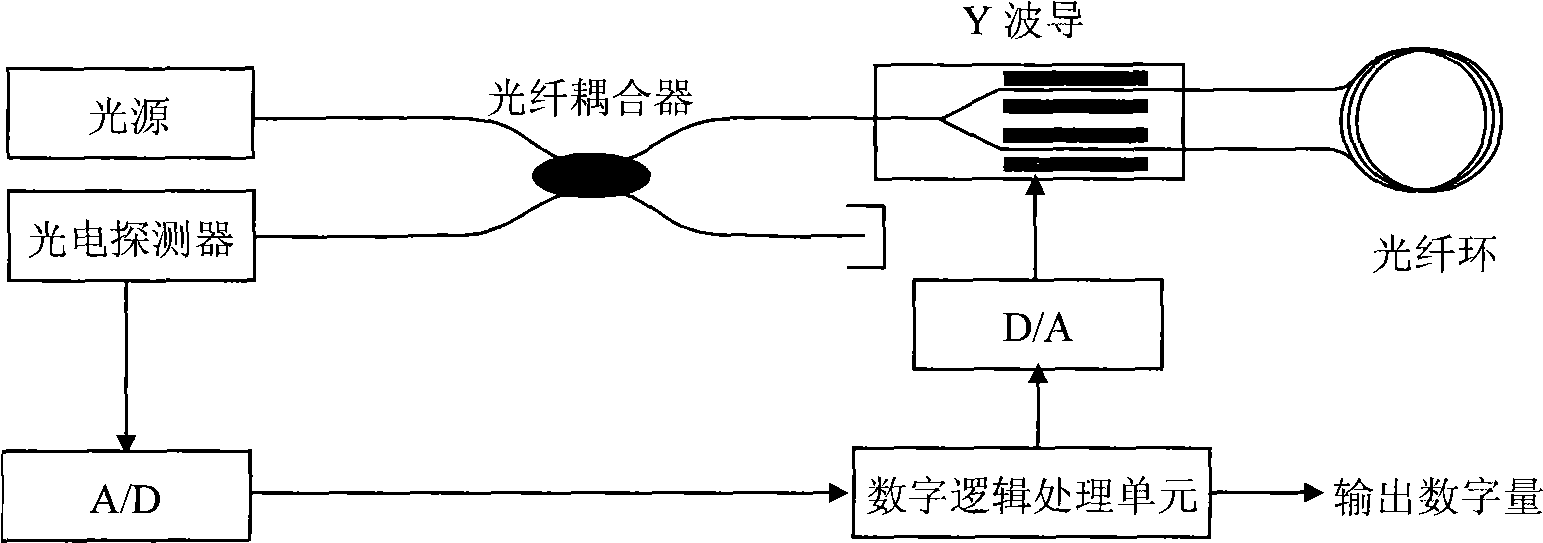
[0024] Such as figure 1 Shown, the test system that the present invention adopts comprises light source, optical fiber coupler, measured Y waveguide, optical fiber ring, photodetector, A / D converter, D / A converter, digital logic processing unit, SLD light source, optical fiber coupling The optical path part of the Sagnac interferometer is composed of the Y waveguide, the fiber ring and the photodetector; the SLD light source or the superfluorescent fiber light source is connected to an input end of the fiber coupler, and the input end of the Y waveguide to be tested is connected to the optical path. The output end of the fiber coupler is connected, the output end of the Y waveguide is connected with the polarization maintaining fiber ring in the optical path, and the photodetector is connected with the other input end of the fiber coupler. The optical signal generated by the light source passes through the optical fiber coupler, the Y waveguide under test and the fiber ring, a...


PUM


Abstract

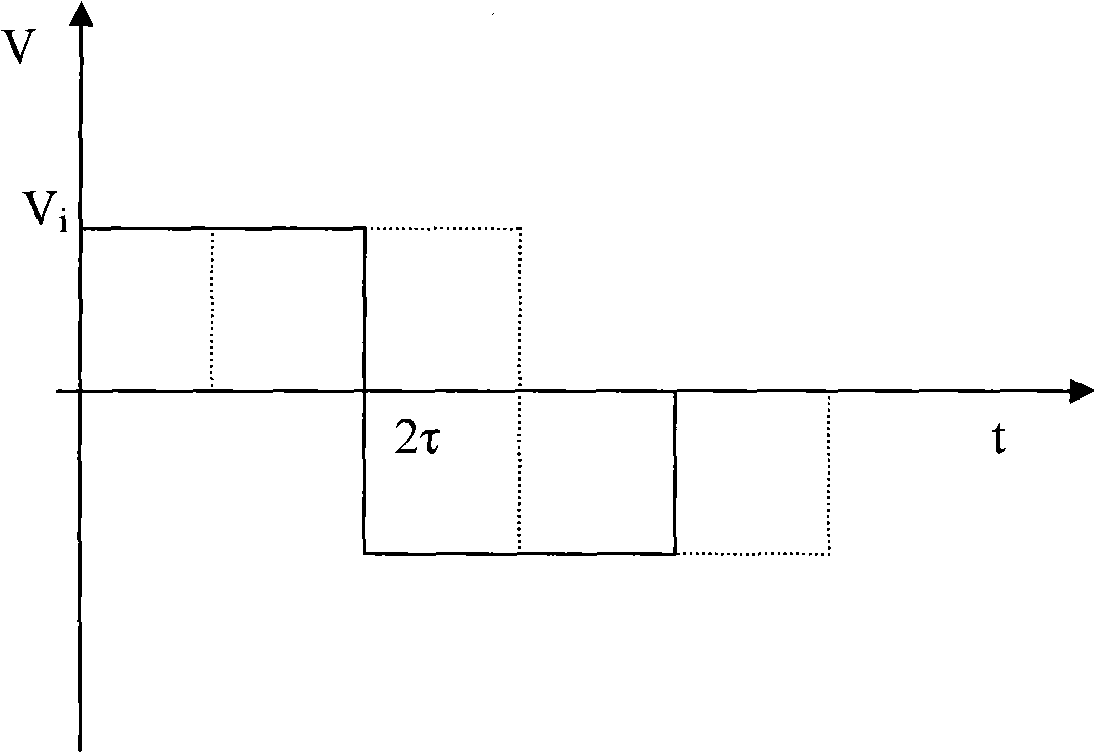
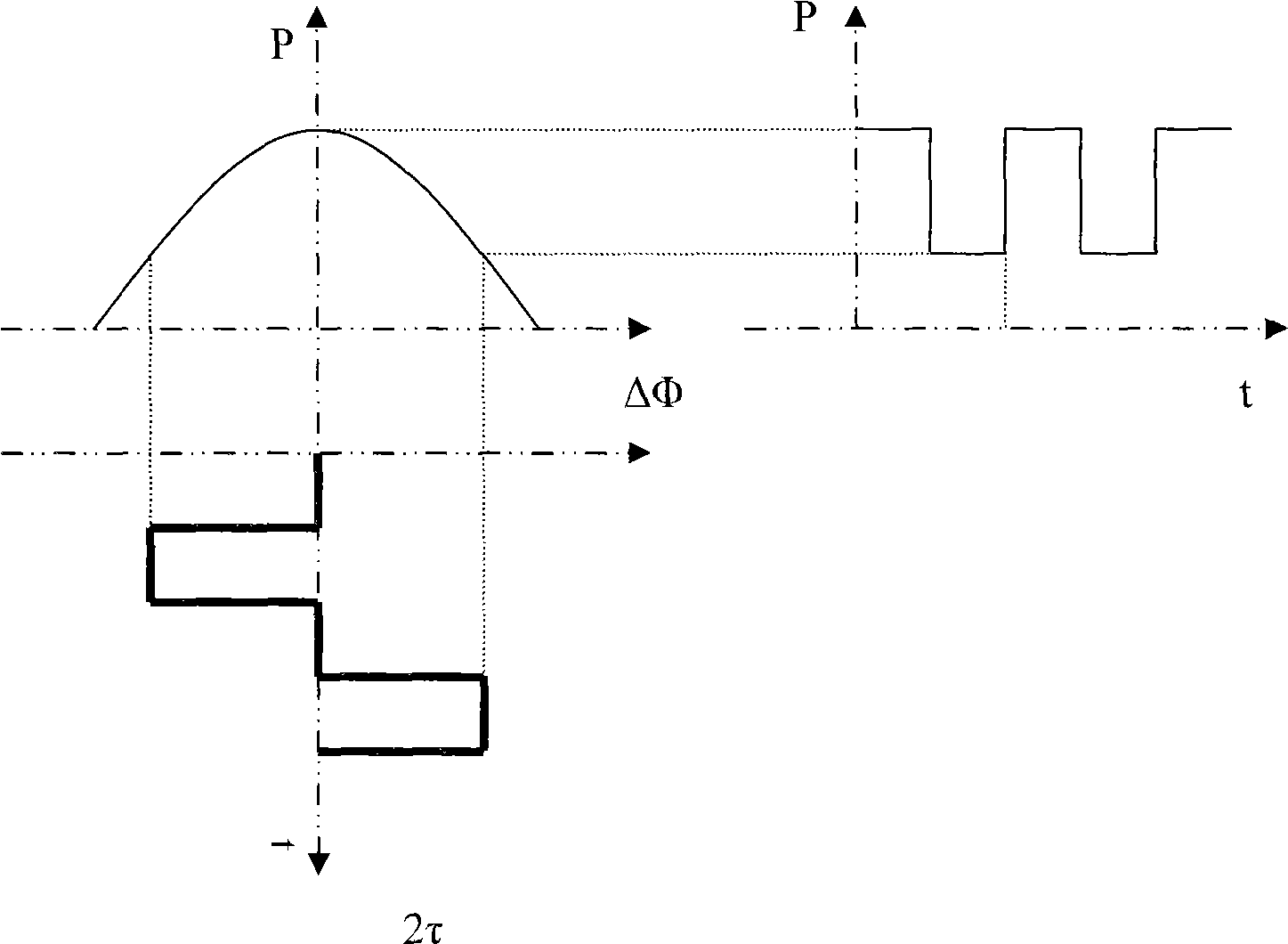
The invention discloses a gamma waveguide phase modulation linearity testing method used for optical fiber gyro, which comprises: composing a testing system by a light source, a optical fiber coupler, a tested gamma waveguide, a optical fiber ring, a photo detector, an A / D converter, an D / A converter and a digital logic processing unit; the digital logic processing unit sending out line form changeable digital square wave with duty ratio of 1:1 to modulate the tested gamma waveguide; and fitting the phase difference of the tested gamma waveguide by least squares method to achieve the modulated linearity. By adopting the square wave with duty ratio of 1:1 with half of the optical fiber ring eigenfrequency to modulate the tested gamma waveguide, increasing the amplitude linearity, and fitting the tested gamma waveguide by least squares method, the invention increases the precision of optical fiber gyro scale factor; meanwhile, by adopting the high accurate D / A converter and A / D converter to modulate and demodulate, the invention increases the testing precision while the phase difference of the tested gamma waveguide is at pi or 2pi.

Description

technical field [0001] The invention relates to a method for testing the linearity of Y-waveguide phase modulation for fiber optic gyroscopes, in particular to a method for testing the linearity of Y-waveguide phase modulation for high-precision fiber optic gyroscopes. Background technique [0002] Fiber optic gyroscope is an all-solid-state inertial instrument, and its accuracy covers applications in various fields of high, medium and low, so it has developed very rapidly in recent years. In the field of medium and high precision, the fiber optic gyroscope adopts a closed-loop solution, which uses a very critical closed-loop device-Y waveguide. The Y waveguide integrates three functions of light splitting / combining, polarization / analysis, and phase modulation. The gyroscope uses the modulation of the Y waveguide to realize the closed loop. By applying a certain voltage on the Y waveguide, a phase difference proportional to the voltage is generated to offset the phase differ...

Claims


Application Information

Patent Timeline
Patent Type & Authority Applications(China)
IPC IPC(8): G01M11/02
Inventor 王巍徐宇新李晶相艳荣于海成丁东发刘福民
Owner BEIJING AEROSPACE TIMES OPTICAL ELECTRONICS TECH
Learn More